Uniform particle airflow generation device and method for flow field tracing

A technology for generating devices and particles, applied in the field of aerodynamic research, can solve problems such as particle deposition and agglomeration, and achieve the effects of avoiding deposition and agglomeration, improving production efficiency, and improving mixing efficiency.

Pending Publication Date: 2021-12-03
中国空气动力研究与发展中心设备设计与测试技术研究所
View PDF0 Cites 4 Cited by
  • Summary
  • Abstract
  • Description
  • Claims
  • Application Information

AI Technical Summary

Problems solved by technology

[0005] An object of the present invention is to provide a uniform particle airflow generating device for flow field tracing, to solve the problems in the prior art in the fluidized bed particle mixing method and the swirl particle mixing method, through the structure The design realizes the combination of the principle of fluidized bed and the principle of swirling strong shear, fully and evenly mixes particles and gas, avoids particle deposition and agglomeration, and can generate uniform particle flow

Method used


Image

  • Uniform particle airflow generation device and method for flow field tracing
  • Uniform particle airflow generation device and method for flow field tracing
  • Uniform particle airflow generation device and method for flow field tracing

Examples


Embodiment 1

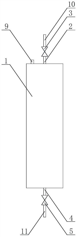
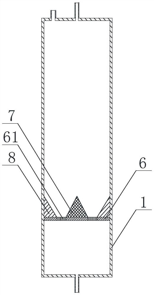
[0054] like Figure 1 to Figure 4 A uniform particle flow generation device for flow field tracing is shown, including a container 1, the top of which is provided with a particle feed port 9 and a gas outlet 2, and the gas outlet 2 passes through a first valve 3 A gas flow guide tube 10 is connected, the bottom of the container 1 is provided with a gas inlet 4, and the gas inlet 4 is connected to a gas source guide tube 11 through a second valve 5, and a first partition is arranged inside the container 1 6. The upper surface of the first partition 6 is provided with an annular body 8 extending along the circumferential direction of the first partition 6, and a cone 7 located inside the annular body 8, the cone 7 and the ring A stacking area for accumulating particles is formed between the shape bodies 8, the width of the stacking area gradually decreases from top to bottom, and an air hole area 61 is also provided on the first partition 6, and an air hole area 61 is arranged o...

Embodiment 2

[0061] On the basis of Example 1, such as Figure 5 , Image 6 and Figure 9 As shown, the bottom of the cone 7 is provided with a driving rod 71, and the lower end of the driving rod 71 moves through the first partition 6, and the driving rod 71 is provided with a lower space located at the first partition 6. The blade 72.

[0062] After the high-pressure gas is filled into the lower space of the first partition through the gas inlet, most of the high-pressure gas hits the tracer particles accumulated in the accumulation area through the first through hole, and a small part of the high-pressure gas hits the blades and drives the drive rod to rotate around its own axis. Drive the cone to rotate. During the rotation of the cone, the tracer particles accumulated on its surface are driven to rotate and move, thereby causing the overall loosening of the accumulated tracer particles, avoiding the deposition and compaction of the tracer particles at the bottom layer, which is not...

Embodiment 3

[0066] On the basis of the above examples, if Figure 5 to Figure 9 As shown, a uniform particle airflow generating device for flow field tracing, the container 1 is provided with a second partition 21 below the first partition 6, and the second partition 21 is provided with several The second through hole 22, the drive rod 71 is provided with a turntable 74 placed on the upper surface of the second partition 21, the turntable 74 is provided with a number of third through holes 76, the turntable 74 can be relatively The second partition 21 rotates, so that the uniform particle flow generating device switches from the pressurized state to the intake state, and switches from the intake state to the pressurized state after the generation of the uniform particle flow is completed;

[0067] In the pressurized state, the second through hole 22 is not aligned with the third through hole 76 , and in the intake state, the second through hole 22 is aligned with the third through hole 76...


PUM


Abstract

The invention discloses a uniform particle airflow generation device and method for flow field tracing, and the device comprises a container, the top of the container is provided with a particle feed inlet and a gas outlet, the gas outlet is connected with an airflow guide pipe through a first valve, the bottom of the container is provided with a gas inlet, and the gas inlet is connected with a gas source guide pipe through a second valve. A first partition plate is arranged in the container, an annular body extending in the circumferential direction of the first partition plate and a cone located on the inner side of the annular body are arranged on the upper surface of the first partition plate, an accumulation area used for accumulating particles is formed between the cone and the annular body, the width of the accumulation area is gradually reduced from top to bottom, and a gas hole area is further arranged on the first partition plate. A plurality of first through holes is formed in the air hole area, and included angles exist between the axes of the first through holes and the axis of the container. The invention has the characteristics of no particle deposition and caking, uniform particle mixing and long particle airflow duration, and is suitable for gas flow fields and combustion flow fields with various speeds and temperatures.

Description

technical field [0001] The invention relates to the technical field of aerodynamic research, in particular to a uniform particle air flow generation device and method for flow field tracing. Background technique [0002] The flow field particle tracer method is widely used in the study of aerodynamic characteristics of various gas flow fields, including cold flow field, heating flow field, combustion flow field, etc. [0003] At present, there are two main ways of mixing tracer particles, one is the fluidized bed particle mixing method, which is easy to form fixed microchannels, the particle content in the particle airflow will gradually decrease with time, and the particles are easy to accumulate The other is the cyclone particle mixing method. Although this method has a strong shearing effect and can effectively reduce particle agglomeration, the particles tend to accumulate directly above the cyclone without swirling flow, causing particles Condensate into lumps in the t...

Claims


Application Information

Patent Timeline
Patent Type & Authority Applications(China)
IPC IPC(8): G06F30/28G06F113/08G06F119/14
CPCG06F30/28G06F2113/08G06F2119/14
Inventor 张俊陈爽齐新华孙运强严来军
Owner 中国空气动力研究与发展中心设备设计与测试技术研究所
Why Eureka
Try Eureka