Self-propelled device for building construction

A technology for building construction, traction devices, used in transportation and packaging, conveyors, mechanical conveyors, etc.

Active Publication Date: 2022-03-18
杨日江
View PDF8 Cites 0 Cited by
  • Summary
  • Abstract
  • Description
  • Claims
  • Application Information

AI Technical Summary

Problems solved by technology

[0005] The technical problem to be solved by the present invention is to provide a self-propelled device for building construction to solve the problem that the existing staff push carts to shuttle back and forth

Method used


Image

  • Self-propelled device for building construction
  • Self-propelled device for building construction
  • Self-propelled device for building construction

Examples


Embodiment 1

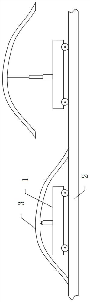
[0035] Such as figure 1 As shown, a self-propelled device for building construction includes a first track 2 and a car body 1, the bottom end of the car body 1 is rollingly connected with the upper end of the first track 2, the number of the car body 1 is more than one, and the upper end of the car body 1 is provided with The second track 3, the first track 2 and the second track 3 are arranged in parallel, the two ends of the second track 3 are respectively lapped on the first track 2, and the two ends of the second track 3 are respectively connected to the upper end of the first track 2 adaptation.

[0036] Specifically, the car body 1 is an electric rail car, the bottom end of the car body 1 is similar to the upper end of the first track 2 and is rollingly connected with the upper end of the first track 2, the first track 2 is a straight track, and the number of the car body 1 is two , the upper end of the car body 1 is equipped with a screw lifter, the lifting end of the ...

Embodiment 2

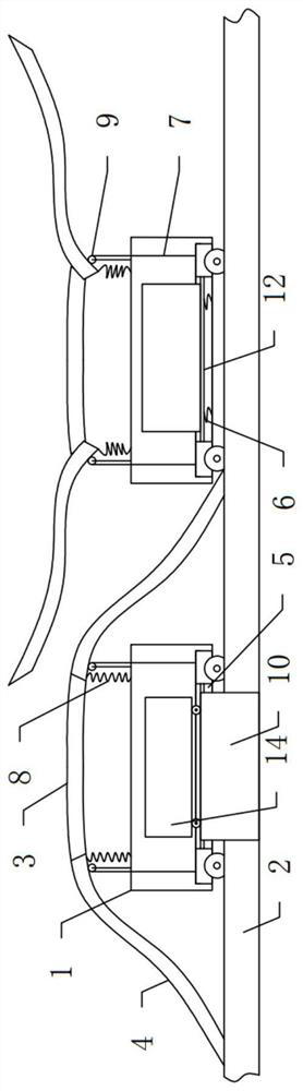
[0038] Such as figure 2 As shown, the structure of this embodiment is roughly the same as that of Embodiment 1, and this embodiment is further optimized on the basis of Embodiment 1: the two ends of the second track 3 are respectively slidably connected with connecting tracks 4, and the connecting tracks 4 are far away from the second track 3 One end of the first rail 2 upper surface fits.

[0039] Specifically, in order to facilitate the interaction between the two car bodies 1, the two ends of the second track 3 are slidably connected to the connecting track 4, and the end of the connecting track 4 away from the second track 3 is adapted to the upper surface of the first track 2. The connecting track 4 is slid and stretched at both ends of the second track 3. When in use, the staff only need to slide the connecting track 4 into or out of the second track 3 to facilitate cross driving. The setting of the sliding connection can facilitate the second Track 3 is retracted to s...

Embodiment 3

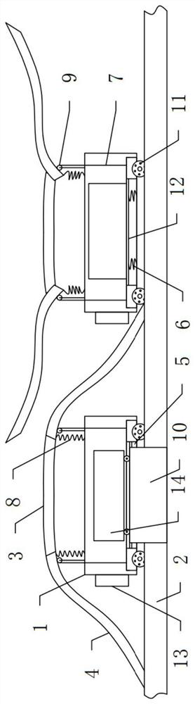
[0045] Such as image 3 , Figure 4 with Figure 5 As shown, the structure of this embodiment is roughly the same as that of Embodiment 2, and this embodiment is further optimized on the basis of Embodiment 2: the first rail 2 and the second rail 3 are both inverted trapezoids with upper ends open.

[0046] Specifically, both the first rail 2 and the second rail 3 are inverted trapezoids with an open upper end, and the driving wheels at the bottom of the car body 1 can be restricted by setting the inverted trapezoid to prevent the car body 1 from leaving the first rail 2 during the movement process. Or the second track 3, the first track 2 and the second track 3 are set in an inverted trapezoid, and at the same time, the two ends of the connecting track 4 can be connected with the first track 2 and the second track 3 respectively, and the setting of the inverted trapezoid can be It is suitable for ordinary vehicles to increase practicality.

[0047] As a further optimizatio...


PUM


Abstract

The self-propelled device for building construction comprises a first rail and more than one vehicle body, the bottom end of the vehicle body is in rolling connection with the upper end of the first rail, a second rail is arranged at the upper end of the vehicle body, the first rail and the second rail are arranged in parallel, and the two ends of the second rail are in lap joint with the first rail respectively. The two ends of the second track are matched with the upper ends of the first tracks respectively. Through the arrangement of the second track, the multiple vehicle bodies can run in a crossed mode, circulating transportation of the multiple vehicle bodies is facilitated, and the working efficiency is improved while the problem that workers push the trolley to shuttle back and forth at present is effectively solved.

Description

technical field [0001] The invention belongs to the field of building construction equipment, in particular to a self-propelled device for building construction. Background technique [0002] With the construction of the city, high-rise buildings rise from the ground. In the construction of high-rise buildings, carts are indispensable in construction as an important means of transportation. In the construction of existing buildings, carts are generally used by staff. Push to move to complete the transportation of building materials, but in the construction process of high-rise buildings, the site is generally large, and the staff need to shuttle back and forth in the construction site to push the cart, and the proportion of personnel use and moving time is relatively large. [0003] The patent with application number CN201710324953.7 proposes a trolley for building construction, which includes a car body, a handrail assembly arranged at one end of the car body, a blocking an...

Claims


Application Information

Patent Timeline
Patent Type & Authority Applications(China)
IPC IPC(8): B65G35/00
CPCB65G35/00Y02T30/00
Inventor 杨日江
Owner 杨日江
Why Eureka
Try Eureka