Clamping equipment and method

A technology of clamping equipment and jaws, which is applied in the field of clamping equipment, can solve the problems of affecting the deflection of shaft parts, affecting the machining accuracy and error of products, and contact asynchrony, so as to ensure the centering accuracy and improve the clamping The effect of precision and stable clamping

Pending Publication Date: 2022-03-25
GUANGZHOU ROVMA AUTO PARTS
View PDF0 Cites 0 Cited by
  • Summary
  • Abstract
  • Description
  • Claims
  • Application Information

AI Technical Summary

Problems solved by technology

[0004] The movement direction of the plane thread on the chainring and the movable claw is close to vertical, and the plane thread on the toothed disk is easy to wear, resulting in an increase in the meshing error between the movable claw and the toothed disk, and resulting in a decrease in the accuracy of self-centering;
[0005] The three-jaw chuck controls the movement of the movable jaw through the drive of the toothed disc. The drive of the movable jaw to each toothed disc is not absolutely synchronous. The difference in synchronization performance is mainly related to the meshing gap between the three-jaw chuck and the toothed disc. (Essentially related to machining accuracy), in actual operation, the contact between the three jaws that are not synchronously moving and the contact surface of the shaft parts is not synchronous, which will also lead to the problem of reduced self-centering accuracy;
[0006] In addition, the problem of the clamping synchronization of the movable jaws will also affect the deflection of the shaft parts. Due to the unbalanced force, the axes of the two shafts will deflect; the processing of the existing shaft parts is using When using a three-jaw chuck, the turning tool is used to rough the surface of the shaft parts. The main purpose is to eliminate the deflection of the shaft parts (readjust the reference coordinate system), and when the shaft parts are processed When performing secondary clamping, the deflection error caused by the clamping will lead to a change in the reference coordinate system. Although the error is small in actual operation, for the high-precision machining field, the error will greatly affect the product. Machining accuracy and error

Method used


Image

  • Clamping equipment and method
  • Clamping equipment and method
  • Clamping equipment and method

Examples


Embodiment Construction

[0042] The following will clearly and completely describe the technical solutions in the embodiments of the present invention with reference to the accompanying drawings in the embodiments of the present invention. Obviously, the described embodiments are only some, not all, embodiments of the present invention. Based on the embodiments of the present invention, all other embodiments obtained by persons of ordinary skill in the art without creative efforts fall within the protection scope of the present invention.

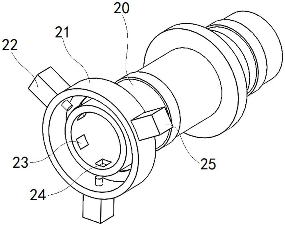
[0043] figure 1 shows a three-dimensional structural schematic diagram of a clamping device according to an embodiment of the present invention, in figure 1 In the shown structure, only the results of a group of auxiliary modules are shown, and other auxiliary modules are not shown in the illustrated structure in order to ensure the clarity of the drawing.

[0044] Correspondingly, the present invention provides a clamping device, including a three-jaw chuck modul...


PUM


Abstract

The invention discloses a clamping device and method, the clamping device comprises a three-jaw chuck module and more than two auxiliary modules, and each auxiliary module comprises three groups of auxiliary units; the three-jaw chuck module comprises a cylindrical bracket and three groups of clamping jaw units which are uniformly arranged along the circumference of the cylindrical bracket; a group of auxiliary units are arranged on the cylindrical bracket at the position opposite to each group of clamping jaw units; in each auxiliary module, at least two auxiliary units in the three auxiliary units are supporting units, each supporting unit comprises a linear driving part, a force feedback element and a clamp head, and the linear driving part drives the clamp head to penetrate through the cylindrical support and move towards or away from the corresponding clamping jaw unit; the force feedback element is used for obtaining surface acting force of the clamp head. According to the clamping equipment, the target workpiece can be pre-clamped through linkage adjustment of the multiple auxiliary units, then the target workpiece is actually clamped through the clamping jaw unit, the centering performance of the clamped target workpiece can be guaranteed, and the clamping precision of the target workpiece is improved.

Description

technical field [0001] The invention relates to the technical field of machine tools, in particular to a clamping device and method. Background technique [0002] At present, three-jaw chucks are generally used as workpiece clamping components on CNC machine tools. Three-jaw chucks refer to the machine tool accessories that use the radial movement of multiple movable jaws evenly distributed on the chuck body to clamp and position the workpiece. . Multiple movable jaws are fitted on the same toothed disc with flat threads, and the movement of each movable jaw will be synchronized under the action of the toothed disc. Generally, the self-centering accuracy of the three-jaw chuck is 0.05-0.15 mm. [0003] In specific use, three-jaw chucks are generally used to clamp shaft parts. In actual implementation, there are the following problems in the clamping of shaft parts by three-jaw chucks: [0004] The movement direction of the plane thread on the chainring and the movable cla...

Claims


Application Information

Patent Timeline
Patent Type & Authority Applications(China)
IPC IPC(8): B23B31/10B23B25/06
CPCB23B31/10B23B25/06
Inventor 罗应涛肖功林钟小华吴雅楠
Owner GUANGZHOU ROVMA AUTO PARTS
Why Eureka
Try Eureka