Wall tile mounting structure

A technology for installing structures and tiles, which is applied in building construction, covering/lining, construction, etc., can solve the problems of increased tile transportation costs, increased tile transportation space requirements, and tiles that cannot be stacked on top of each other, so as to reduce the risk of falling , Improve decoration efficiency and save assembly time

Pending Publication Date: 2022-05-06
ZHEJIANG YASHA DECORATION
View PDF0 Cites 0 Cited by
  • Summary
  • Abstract
  • Description
  • Claims
  • Application Information

AI Technical Summary

Problems solved by technology

This has just produced a kind of new problem, is exactly in order to guarantee the stability that tile is installed on the wall, need just be fixed on the back of ceramic tile when leaving factory, to guarantee that the installation position of connecting member on the back of tile will not produce Excessive deviation, because the connecting member occupies a certain space on the back of the tiles, the tiles cannot be stacked on each other, resulting in an increase in the demand for tile transportation space, resulting in an increase in the transportation cost of the tiles

Method used


Image

  • Wall tile mounting structure
  • Wall tile mounting structure
  • Wall tile mounting structure

Examples


Embodiment 1

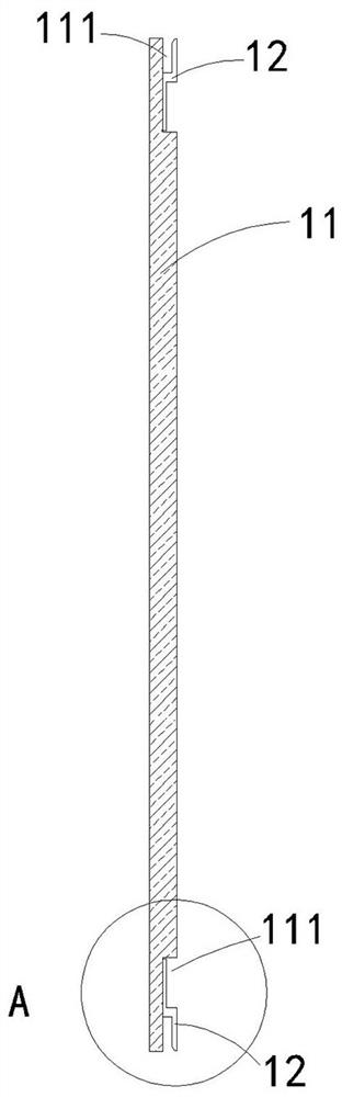
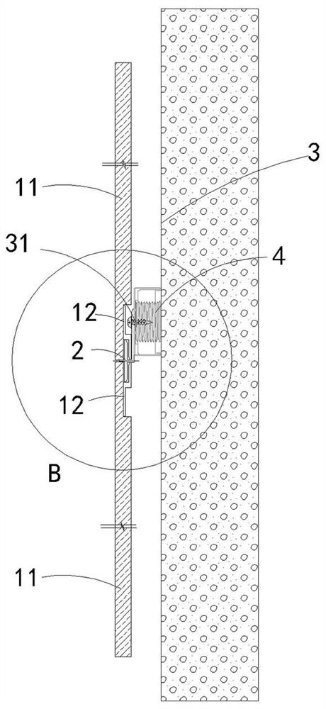
[0035] see Figure 1-4 7. This embodiment provides a wall tile installation structure, including at least two tile units and connectors 2, the number of connectors 2 is one less than the number of tile units, and all tile units are arranged in sequence along the vertical direction, A connecting piece 2 is provided between every two adjacent tile units, so that two adjacent tile units are connected through the connecting piece 2 . The tile unit and connector 2 are transported to the decoration site respectively, and the tile unit and connector 2 are assembled at the decoration site to form a wall tile installation structure, and the connector 2 is installed on the wall 3, so that the tile unit can pass through the connection. The piece 2 lays the wall surface 3 . Conventionally, a leveling piece 4 is arranged between the connecting piece 2 and the wall surface 3 in this embodiment, and the connecting piece 2 is installed on the wall surface 3 through the leveling piece 4 .

[...

Embodiment 2

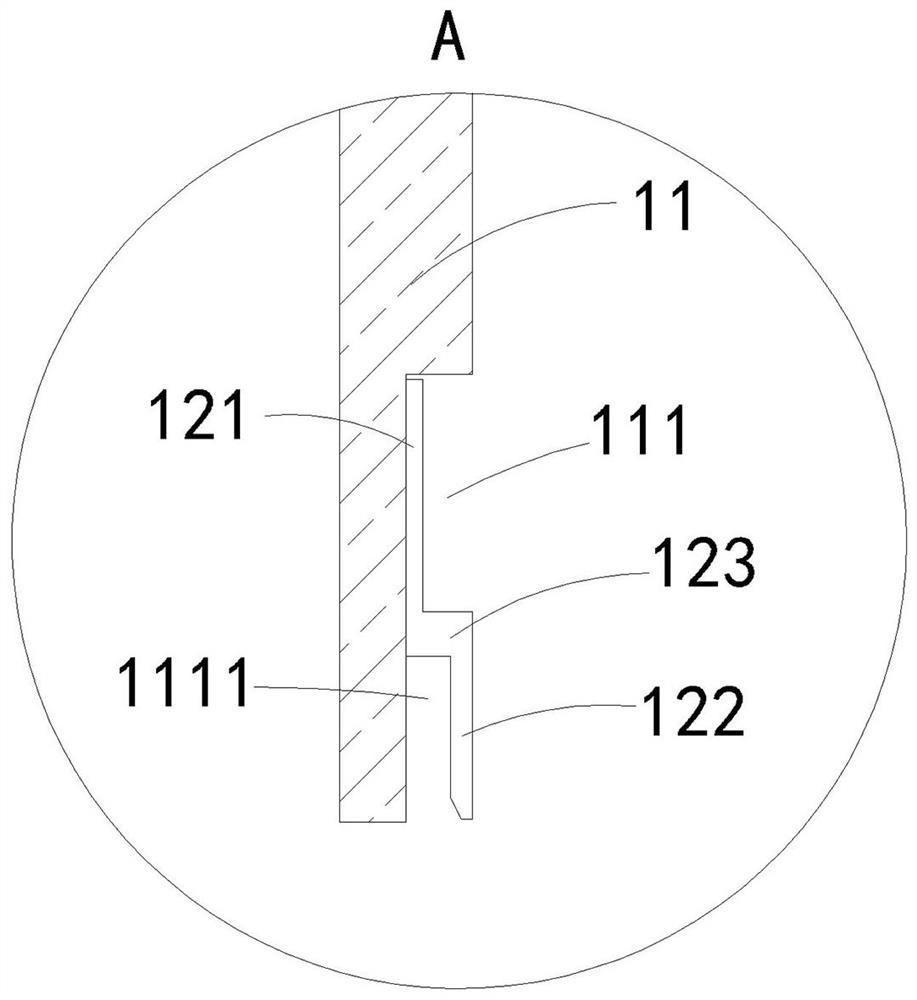
[0061] see Figure 5-7 In this embodiment, the clamping member also includes a sticking plate 121, a clamping plate 122 and a component connecting plate 123, the edge of the sticking plate 121 is fixed to the front side edge of the component connecting plate 123, and the edge of the clamping plate 122 is connected to the component connecting plate The rear side edge of 123 is fixed, and the pasting plate 121 is glued and fixed to the inner wall of the receiving groove 111 . The difference between this embodiment and Embodiment 1 is that the pasting plate 121 and the clamping plate 122 are located on the same side of the component connecting plate 123, and among the clamping components on the top of the tile unit, the pasting plate 121 and the clamping plate 122 are both located on the component connecting plate 123. Above the board 123 , among the clamping components at the bottom of the tile unit, the pasting plate 121 and the clamping plate 122 are both located below the com...


PUM


Abstract

The invention discloses a wall tile mounting structure. The wall tile mounting structure comprises at least two tile units and a connecting piece, each ceramic tile unit comprises a ceramic tile and two clamping components, containing grooves are formed in the top and the bottom of the back face of the ceramic tile, and the two clamping components adhere to the inner walls of the two containing grooves correspondingly, so that the clamping components are located in the containing grooves, and inserting grooves are formed in the containing grooves; the connecting piece comprises an upper inserting plate, a lower inserting plate and a base plate. The containing groove is formed in the back face of the ceramic tile in a grooving mode, it is ensured that no or only a small amount of magnesium oxide powder exists in the containing groove, and therefore the clamping component can be installed in the containing groove in a pasted mode, the clamping component is effectively prevented from falling off from the inner wall of the containing groove in the later period, and the risk that the ceramic tile falls off from the wall face is reduced; and the safety is effectively ensured.

Description

technical field [0001] The invention relates to a wall tile installation structure, which belongs to the field of wall installation. Background technique [0002] The traditional installation of wall tiles is pasted to the wall or leveling parts with tile glue. Due to the production process of the tiles itself, there is a certain amount of magnesium oxide powder on the back of the tiles. Before pasting, the back of the tiles needs to be cleaned. Clean up, otherwise the tiles are easy to fall off after pasting, resulting in potential safety hazards. [0003] In order to eliminate the above-mentioned hidden dangers, the prior art provides the following way to install the tiles on the wall. Specifically, the connecting member is fixed on the back of the tile by screws, and then the connecting member is fixed on the wall by screws. This has just produced a kind of new problem, is exactly in order to guarantee the stability that tile is installed on the wall, need just be fixed ...

Claims


Application Information

Patent Timeline
Patent Type & Authority Applications(China)
IPC IPC(8): E04F13/072E04F13/26E04F13/28
CPCE04F13/08E04F13/0855E04F13/0857E04F13/142
Inventor 丁欣欣丁泽成王文广钟诚应李攀黄永欢李秋彤李建斌
Owner ZHEJIANG YASHA DECORATION
Why Eureka
Try Eureka