Adjustable composite damping rubber pad

A shock-absorbing rubber pad and adjustable technology, applied in the field of rubber pads, can solve the problems of inconvenient processing, limited rigidity range, different rigidity requirements, etc. Effect

Active Publication Date: 2022-07-29
海门市华洋汽车配件制造有限公司
View PDF8 Cites 0 Cited by
  • Summary
  • Abstract
  • Description
  • Claims
  • Application Information

AI Technical Summary

Problems solved by technology

Although the above-mentioned schemes can meet certain requirements for vibration-reducing support, if you want to change its load-bearing capacity and elasticity, for the schemes of application number CN201620022210.5 and application number CN201720501765.2, it can only be achieved by changing the hardness of the rubber. At this time, the creep resistance of the rubber will also change accordingly. Although it is mentioned in the scheme of application number CN202011049540.0 that the stiffness is adjusted by setting through grooves and through holes (paragraph 43 of the specification), when the stiffness adjusted in this way The range is very limited, especially for small-volume rubber pads. To achieve a slightly larger range of stiffness adjustment, it is still necessary to change the hardness of the rubber at the same time, and this method will make the rubber pad molding mold structure complicated. It is inconvenient to process, that is to say, when the use environment changes, the above scheme will seriously affect the vibration damping support effect and service life of the rubber pad, so it can only be used in a single environment. Different environments will have different usage requirements, such as different load requirements, different rigidity requirements, etc., and the existing structure is difficult to meet such usage requirements. Therefore, we propose an adjustable composite shock-absorbing rubber pad to solve the above problems

Method used


Image

  • Adjustable composite damping rubber pad
  • Adjustable composite damping rubber pad
  • Adjustable composite damping rubber pad

Examples


Embodiment 1

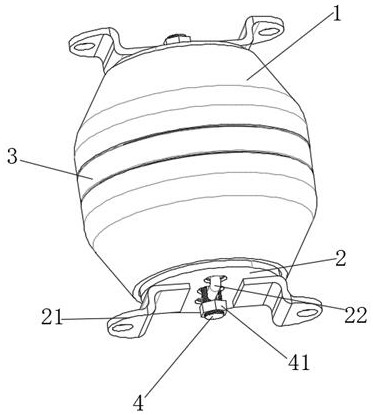
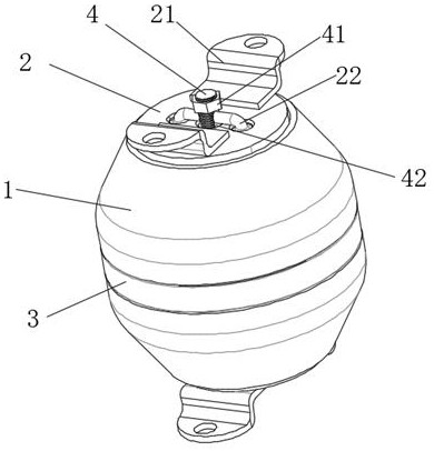
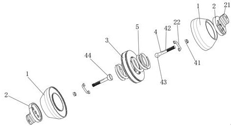
[0042] see Figure 1-9 , an adjustable compound shock-absorbing rubber pad, comprising two oppositely arranged rubber pads 1, a buffer device 3 is arranged between the two rubber pads 1, the buffer device 3 includes a flexible rubber sleeve 31, and the flexible rubber sleeve 31 is provided with Two groups of friction rings 32, the friction rings 32 are annular structures with an L-shaped cross-section, the two friction rings 32 are interlockingly arranged, and the sides away from the two friction rings 32 are respectively fixedly connected with the rubber pad 1, and the friction rings 32 A fixed magnetic ring 323 is provided on one side of the circular ring of the friction ring 32, and a cavity is provided on the other side of the circular ring of the friction ring 32. The sliding magnetic ring 33 is slidably connected in the cavity. The sliding magnetic ring 33 has the same magnetic properties as the fixed magnetic ring 323. A return spring 34 is sandwiched between the slidin...


PUM


Abstract

The invention discloses an adjustable composite damping rubber pad, and belongs to the field of rubber pads, the adjustable composite damping rubber pad comprises two oppositely arranged rubber pads, a buffer device is arranged between the two rubber pads, the buffer device comprises a flexible rubber sleeve, two groups of friction rings are arranged in the flexible rubber sleeve, the friction rings are of a circular ring structure with an L-shaped section, and the friction rings are arranged in the flexible rubber sleeve. The two friction rings are arranged in a buckled mode, the sides, away from each other, of the two friction rings are fixedly connected with the rubber pad, a fixed magnetic ring is arranged on one side of a circular ring of each friction ring, a cavity is formed in the other side of the circular ring of each friction ring, a sliding magnetic ring is slidably connected into each cavity, and the magnetism of the sliding magnetic rings is the same as that of the fixed magnetic rings. According to the rubber pad, the compression deformation quantity of the rubber pad can be effectively reduced, the service life of the rubber pad is prolonged, and the rubber pad has market prospects and is suitable for popularization.

Description

technical field [0001] The invention relates to the field of rubber pads, and more particularly, to an adjustable composite shock-absorbing rubber pad. Background technique [0002] Rubber pad is a widely applicable metal-rubber structure, which is widely used in places that need to provide vibration damping support. (For example, the application number CN201720501765.2, the utility model patent named "An axial composite rubber pad"; the application number CN202011049540.0, the invention application named "An axial rubber pad and a cross-support bogie"), etc. . Although the above solutions can meet certain vibration damping support requirements, to change the load-bearing capacity and elasticity, for the solutions with application numbers CN201620022210.5 and CN201720501765.2, it can only be achieved by changing the hardness of the rubber. At this time, the creep resistance of the rubber will also change accordingly. Although the proposal of the application number CN202011...

Claims


Application Information

Patent Timeline
Patent Type & Authority Applications(China)
IPC IPC(8): F16F15/08F16F15/023F16F15/02
CPCF16F15/085F16F15/023F16F15/022F16F15/02
Inventor 吴亮
Owner 海门市华洋汽车配件制造有限公司
Why Eureka
Try Eureka