Zip fastener

一种拉链、拉链带的技术,应用在拉链领域,能够解决不协调等问题

Inactive Publication Date: 2006-07-26
YKK CORP
View PDF4 Cites 0 Cited by
  • Summary
  • Abstract
  • Description
  • Claims
  • Application Information

AI Technical Summary

Problems solved by technology

At this time, some people may feel uncoordinated, because the hard feeling of the upper stopper will be transmitted to the fingers

Method used


Image

  • Zip fastener
  • Zip fastener
  • Zip fastener

Examples


Embodiment Construction

[0021] Exemplary embodiments of the present invention will be described below with reference to the accompanying drawings.

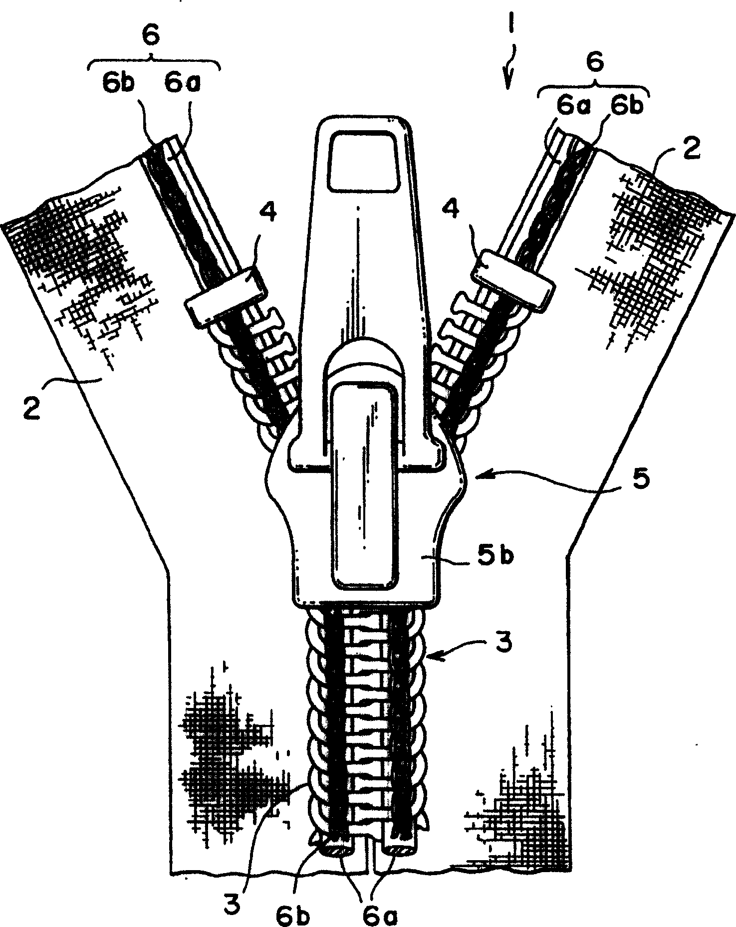
[0022] figure 1 The end portion on the upper stopper side of the slide fastener of the present invention is shown. Such as figure 1 As shown, the fastening element 3 is mounted on the side edge of the fastener tape 2 . Usually, an upper stopper is installed as a stopper portion of the slide fastener 1 at the end of the slide fastener on the closing side, and a lower stopper is installed at the end of the opening side as another stopper portion (not shown).

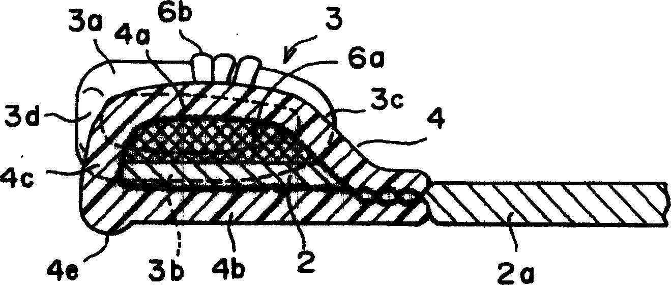
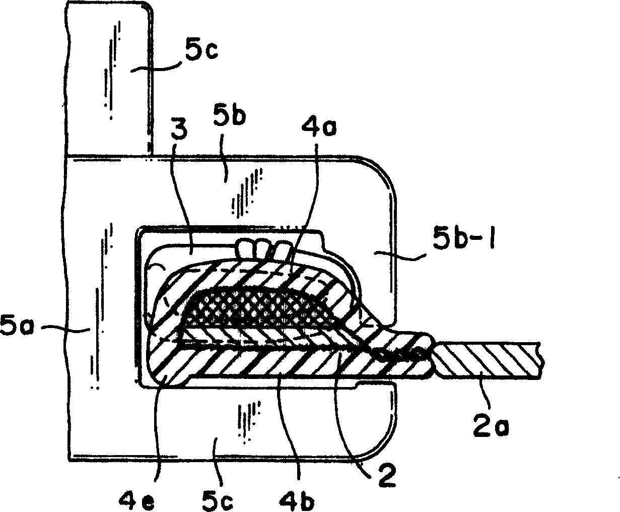
[0023] Like the stopper portion described in the aforementioned Japanese Utility Model Application No. 62-148116 and Japanese Utility Model Application No. 5-31932, the stopper portion 4 as the aforementioned upper stopper includes: an upper leg portion 4a and The lower leg portion 4b, the upper leg portion 4a and the lower leg portion 4b sandwich the front and rear sides of the fastener tape; and...


PUM


Abstract

A stopper portion (4) has a minute protrusion on part of an outer peripheral face except a side face in the length direction of a fastener tape (2). This protrusion is a rib-like protrusion (4f) extended linearly in the length direction of the fastener tape formed on a vertex of the surface of a bent portion (4c), a protrusion (4g) extended so as to be expanded in a curved shape in the length direction of the fastener tape or a rib-like protrusion (4e) protruded along a boundary portion between the bent portion of the stopper portion (4) and a bottom face thereof. Existence of this protrusion not only reduces a sliding resistance when the slider is started but also eliminates prickly feeling and feeling of disharmony originating from a shape of an upper stopper which is a kind of the conventional stopper portion.

Description

technical field [0001] The present invention relates to a slide fastener in which a stopper portion is molded on a fastener tape by melting a resin stopper material having a U-shaped section under pressure by ultrasonic heating, high-frequency heating, or heater heating, This heater is adjacent to the fixing elements mounted on the side edges of the zipper tape. Background technique [0002] Generally, as an upper stopper provided by melting a resin material, a film-like or monofilament-like material is mounted on the top surface of the fastener tape or the fixing member by a welding method. For example, for the upper stopper of a slide fastener described in Japanese Patent Application No. 48-37421, a monofilament made of thermoplastic synthetic resin such as polyester resin or polyamide resin is cut to a predetermined length, bent into a U shape, And it is installed on the inverting part or the foot part of the coil-shaped fixing element by welding and pressing. For the u...

Claims


Application Information

Patent Timeline
Patent Type & Authority Patents(China)
IPC IPC(8): A44B19/36A44B19/38
CPCA44B19/36A44B19/386Y10T24/2598Y10T24/2518Y10T24/2511
Inventor 近藤直希吉田米雄外石义行前田英二
Owner YKK CORP
Why Eureka
Try Eureka