

Rice cooker
A technology for a rice cooker and a placing part is applied in the directions of cooking utensils, the structure of cooking utensils, special materials of cooking utensils, etc., which can solve the problems of resin strength deterioration, resin deterioration, resin yellowing, etc., and achieves easy cleaning and improved product performance. , the effect of easy recycling
- Summary
- Abstract
- Description
- Claims
- Application Information
AI Technical Summary
Problems solved by technology
Method used
Image


Examples
Embodiment 1
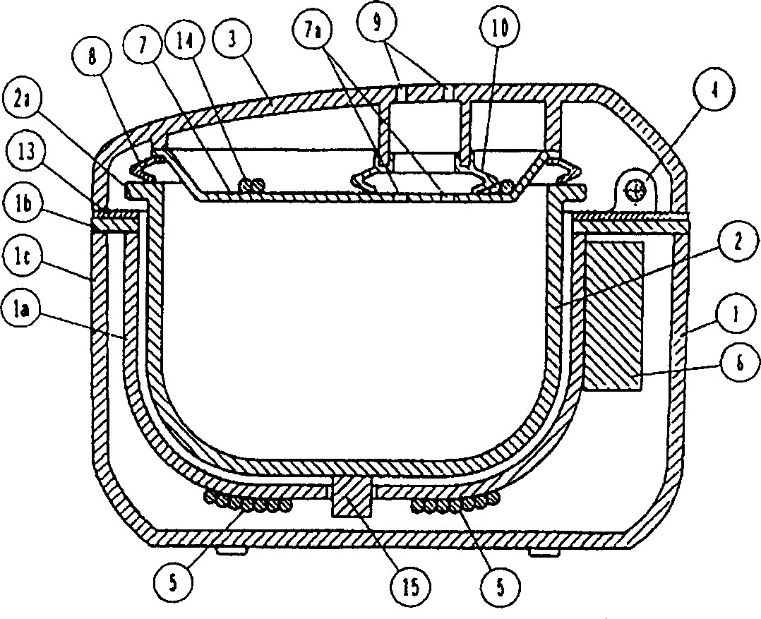
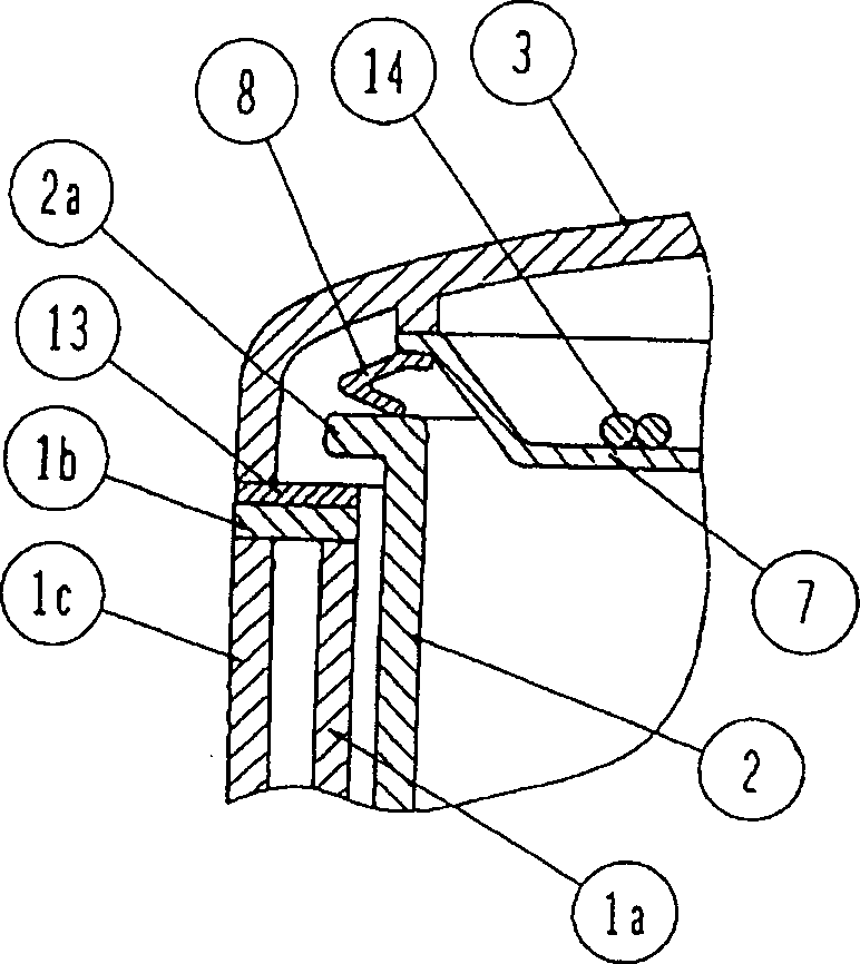
[0073] refer to Figure 1 to Figure 5 Examples of the present invention will be described. The rice cooker main body 1 has a bottomed cylindrical pot placement part 1a, and the pot placement part upper edge part 1b is connected to the upper end part of the pot placement part 1a. The outer periphery of the pan rest upper edge part 1b is supported by the outer peripheral wall surface part 1c. Moreover, the metal main body cover 13 is arrange|positioned on the upper surface of the pan mounting part upper edge part 1b.
[0074] The pot 2 is detachably placed on the main body from above, and the outer peripheral flange portion 2a of the pot 2 is positioned above the upper edge portion 1b of the pot placement portion when the pot 2 is placed on the pot placement portion 1a of the main body 1 ( figure 2 ).
[0075]The pot 2 is heated by the heating coil 5 in an induction heating manner to cook and keep warm. Reference numeral 6 is a control unit for controlling the heating opera...
Embodiment 2
[0086] refer to Figure 8 ~ Figure 12 Examples of the present invention will be described. The rice cooker main body 101 has the bottomed cylindrical pot placement part 101a, and the pot placement part upper edge part 101b is connected to the upper end part of the pot placement part 101a. The outer periphery of the pan mounting part upper edge part 101b is supported by the outer peripheral wall surface part 101c. Furthermore, the main body cover 113 is arrange|positioned on the upper surface of the pan mounting part upper edge part 101b.
[0087] The pot 102 is detachably placed on the pot placement part 101a from above, and the outer peripheral flange part 102a of the pot 102 is positioned above the upper edge part 101b of the pot placement part when the pot 102 is placed on the pot placement part 101a of the main body 101 ( Figure 9 ).
[0088] The pot 102 is heated by induction heating by the heating coil 105 to cook and keep warm. Reference numeral 106 is a control un...
Embodiment 3
[0099] refer to Figure 13 to Figure 19 Embodiment 3 of the present invention will be described. The rice cooker main body 201 has a bottomed cylindrical pot placement part 201a, and the pot placement part upper edge part 201b is connected to the upper end part of the pot placement part 201a. The outer periphery of the pot rest upper edge part 201b is supported by the outer peripheral wall surface part 201c. Furthermore, the main body cover 213 is arrange|positioned on the upper surface of the pan mounting part upper edge part 201b.
[0100] The pot 202 is detachably placed on the pot placement part 201a from above, and the outer peripheral flange part 202a of the pot 202 is positioned above the upper edge part 201b of the pot placement part when the pot 202 is placed on the pot placement part 201a of the main body 201 ( Figure 14 ).
[0101] The pot 202 is heated by the heat generated by the bottom heater 205 to cook rice and keep it warm. Reference numeral 206 is a cont...
PUM
 Abstract
Description
Claims
Application Information