Door lock

A door lock and latch technology, applied in the field of door locks, can solve the problems of time-consuming and lengthy assembly, and achieve the effects of easy combination, improved safety and convenient installation

Inactive Publication Date: 2003-07-02
TLHM CO LTD
View PDF0 Cites 2 Cited by
  • Summary
  • Abstract
  • Description
  • Claims
  • Application Information

AI Technical Summary

Problems solved by technology

In addition, when some door locks need to replace the inner handle on certain occasions, because the switch button is directl

Method used


Image

  • Door lock
  • Door lock
  • Door lock

Examples


Embodiment Construction

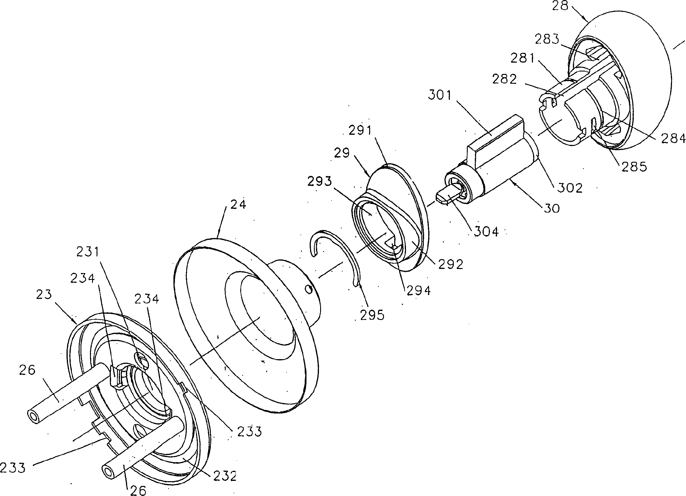
[0033] Such as figure 1 , 2 , 3 and 4, an outer handle 28 is generally generally in the shape of an ellipsoid (or oblate spheroid or L-shaped wrench, shown as an ellipsoid in the figure) and is hollow inside, with an axially extending shaft tube 281, The tube wall of the shaft tube 281 has an axial groove 282 connected to the lateral groove 283 formed laterally on the ellipsoid to accommodate a lock cylinder 30 with a lateral protrusion 301, a plunger 302 is inserted inside the lock cylinder 30, and the cylinder One end of the plug 302 can be inserted by a key (not shown in the figure), and the other end along the axial direction is connected with a key 304 . The plunger 302 can be operated by a correct key (not shown) to rotate in the lock cylinder 30 . An outer handle cover 29 has an elliptical plate body 291 connected to the axial annular protrusion 292, and its central position has a hole 293, and two grooves 294 are formed at the opposite positions of the peripheral wal...


PUM


Abstract

A door lock features that the bearing nut of external sleeve disk passes through the locating element of lock bolt, the lock bolt is engaged with the external sleeve disk, two opposite arc ends of two arced surfaces of the said locating element are just engaged with a lock bolt mechanism, and the said bearing nut just passes through the lock bolt mechanism and then is inserted in the sleeve rod of internal sleeve disk. Its advantages are easy assembling, high torsional strength, and high safety.

Description

technical field [0001] The invention relates to a door lock, in particular to a positioning structure of the outer casing of the door lock and a door locking mechanism, and a positioning structure of a switch button and an inner driving tube of the door lock. Background technique [0002] Some door lock outer sleeves and latch mechanisms are combined with a positioning sleeve structure directly formed on the outer sleeve of the door lock. When the door lock is to be installed on the door panel, it may be because the opening size of the door panel cannot be adjusted. Fits exactly the size of the positioning sleeve without being able to fit. [0003] Some door locks are provided with a detachable positioning sleeve, and the door lock and the positioning sleeve are combined with an elastic steel wire or steel plate, or combined with screws, and these combinations need to be completed with auxiliary tools when disassembled. In addition, when some door locks need to replace the ...

Claims


Application Information

Patent Timeline
IPC IPC(8): E05B55/14
Inventor 陈柏仰
Owner TLHM CO LTD
Why Eureka
Try Eureka