Image forming apparatus

An image and reading device technology, which is applied in the direction of electric recording process applying charge pattern, equipment for electric recording process applying charge pattern, electric recording technique, etc. question

Inactive Publication Date: 2004-04-07
BROTHER KOGYO KK
View PDF1 Cites 2 Cited by
  • Summary
  • Abstract
  • Description
  • Claims
  • Application Information

AI Technical Summary

Problems solved by technology

However, when installing each part, for example, when the frame of the recording module with the operation module is made of metal and the operation module is made of resin, the mutual thermal

Method used


Image

  • Image forming apparatus
  • Image forming apparatus
  • Image forming apparatus

Examples


Embodiment Construction

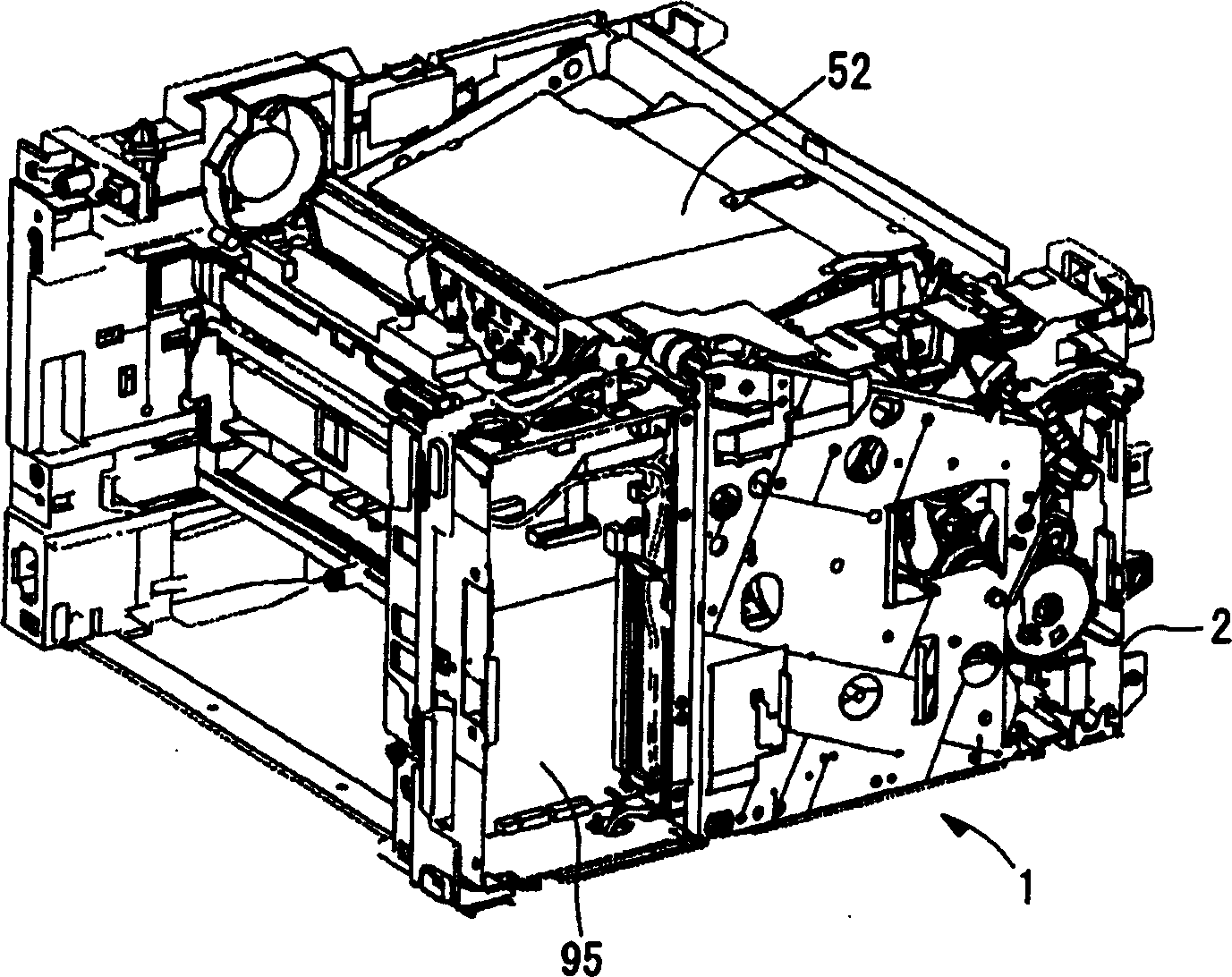
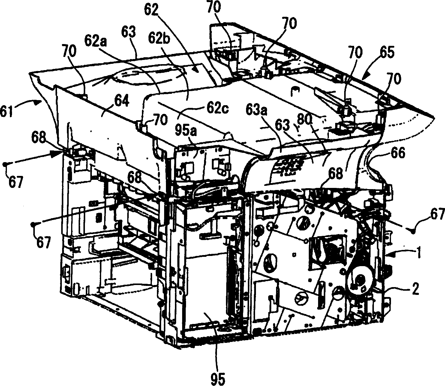
[0111] Figure 12 with Figure 13 It is a perspective view showing a compound machine F as an embodiment of the image forming apparatus of the present invention. The multifunctional machine F is equipped with a flatbed scanner unit 81 as an image reading unit on the printer body 1, which is the main body of the image forming apparatus, and has functions of printing, copying, facsimile, and network communication.

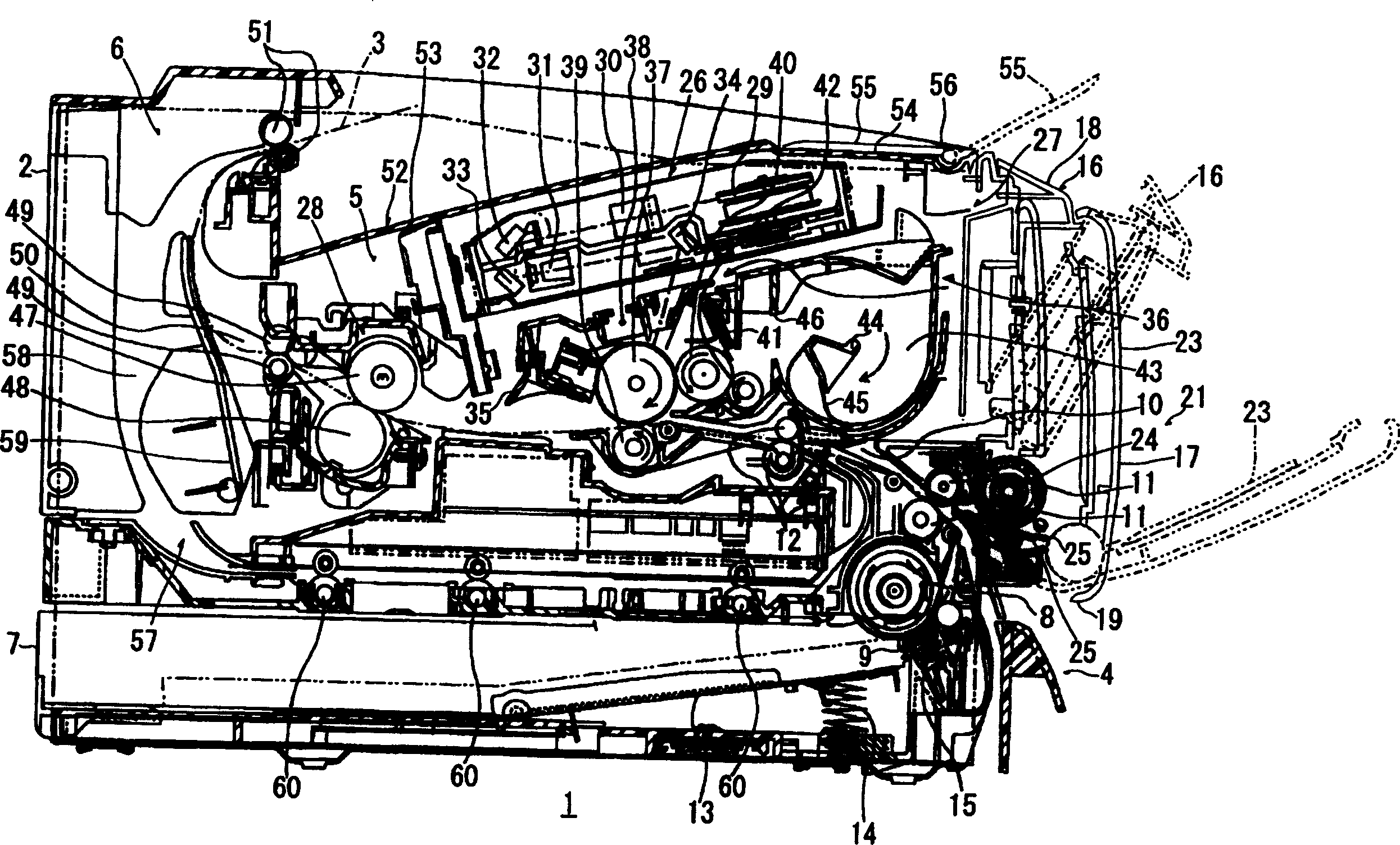
[0112] figure 1 It is a side sectional view of main parts showing an embodiment of the printer body 1 . First, refer to figure 1 The printer body 1 will be described.

[0113] figure 1 Among them, the printer main body 1 is a structure of a laser printer. In the main body frame 2 made of resin, there are a paper feeding part 4 for feeding paper 3 as a recording medium, and a paper feeding part 4 for discharging paper 3. An image forming section 5 on which an image is formed, a paper discharge section 6 for discharging the paper 3 on which an image is formed,...


PUM


Abstract

To improve the rigidity of an image forming apparatus provided with an ejection part between an image reading device and an image forming apparatus body. Since a joint cover 61 is attached to a printer body 1, and a scanner unit 81 is supported by the joint cover 61, a connection part consisting of the joint cover 61 between the printer body 1 and the scanner unit 81 is made as a paper ejecting part 99 to eject paper 3, and the front end of the side cover 63 of the joint cover 61 is arranged on the front side of the front end 82a of an original platen 82, so that a front end recess 66 recessed on a backside is formed at the front end. Thus, the ejected paper 3 is easily taken out from the recess of the front end recess 66 while supporting the scanner unit 81 by the side cover 63, and the improvement of operability is attained while securing the rigidity of the apparatus.

Description

technical field [0001] The present invention relates to an image forming apparatus having an image reading device. Background technique [0002] Conventionally, in equipment such as facsimile machines and copiers, there is known a structure in which an image reading device for reading an image recorded in a document is mounted on the upper portion of the image forming apparatus body. [0003] As such an image forming apparatus, for example, in Japanese Patent No. 3205734 (Patent Document 1), it is described as follows: Figure 21 Shown is a proposal of an image forming apparatus 150 having an image forming apparatus main body 151 and an ADF (Automatic Document Feeder) unit 152 disposed on the upper portion of the main body. [0004] In this image forming apparatus 150, a carbon paper discharge unit 153 is provided on the upper portion of the main body 151, that is, at the middle portion in the depth direction between the main body 151 and the ...

Claims


Application Information

Patent Timeline
IPC IPC(8): G03G15/00
CPCG03G15/60G03G2215/0021
Inventor 龟山宜克洞口洋一片山重治星屋和弘
Owner BROTHER KOGYO KK
Why Eureka
Try Eureka