

Motorcycle muffler of dispaceable catalytic converter
A catalytic converter and muffler technology, which is applied in the direction of mufflers, machines/engines, engine components, etc., can solve problems such as inability to take out, and achieve the effects of easy disassembly, simple and convenient installation and fast installation
- Summary
- Abstract
- Description
- Claims
- Application Information
AI Technical Summary
Problems solved by technology
Method used
Image

Examples
Embodiment 1
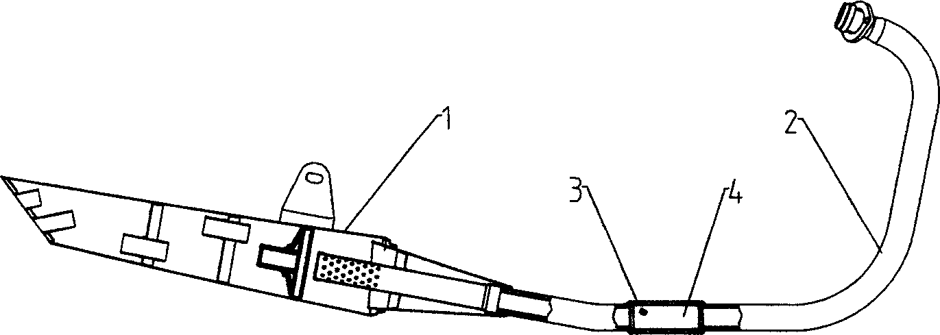
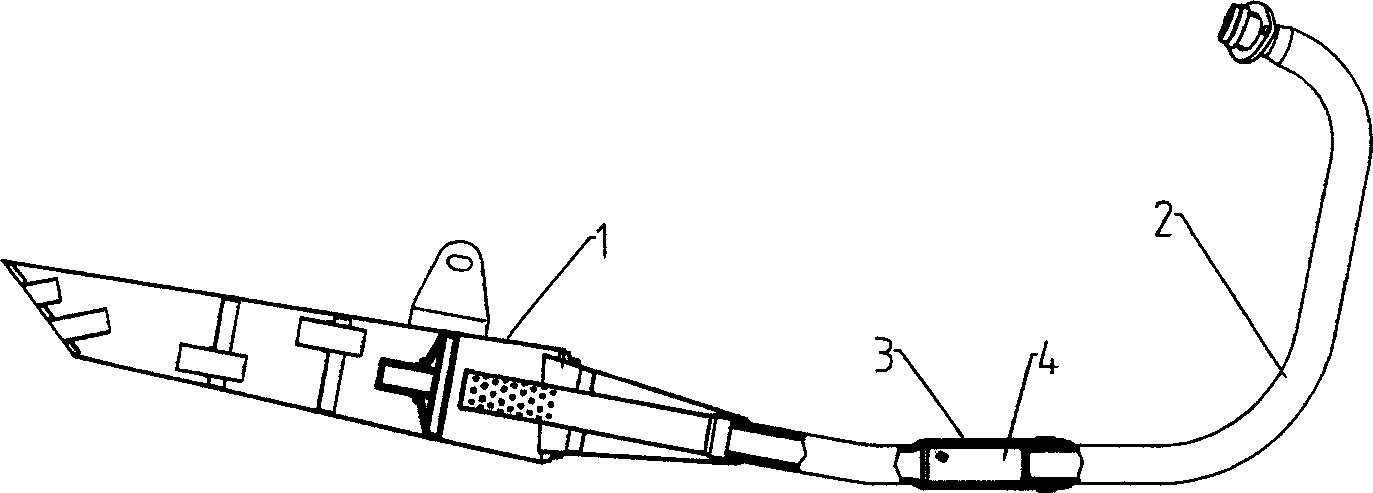
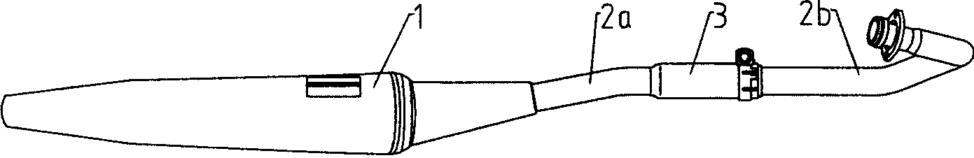
[0028] Such as Figure 2 to Figure 6 As shown, the motorcycle muffler is composed of a muffler part 1 and an exhaust pipe. The exhaust pipe adopts a split design and is divided into two sections 2a, 2b. The end of the exhaust pipe 2a directly connected to the muffler part 1 is expanded by an expansion tool to make its inner diameter larger to form a catalytic converter fixed pipe 3, and the catalytic converter fixed pipe 3 is connected to the exhaust pipe 2b by a hoop connection. There are four (or other numbers) axial slots 32 at the connecting end of the catalytic converter fixing pipe 3, and the end of the connecting end of the exhaust pipe 2b connected thereto is inserted into the connecting end of the catalytic converter fixing pipe 3, and two A sealing element 6 is installed between them, and the connecting end of the catalytic converter fixing pipe 3 is fastened by a hoop 5 outside.
[0029] A step 31 is processed at the connecting end of the catalytic converter fixed ...
Embodiment 2
[0034] Such as Figure 7 As shown, the present embodiment is different from Embodiment 1 in that the catalytic converter fixed pipe 3 is an independent pipe section, and the diameter of this pipe section is larger than the diameter of the exhaust pipe 2a, 2b of the muffler, and the catalytic converter fixed pipe 3 is two The ends are respectively connected to the exhaust pipes 2b and 2a through hoops 5, 5', and the connection structure is exactly the same as the hoop connection structure in Embodiment 1, and will not be repeated in this embodiment. Compared with Example 1, this structure only needs to disassemble two bolts 6 and 6' when the catalytic converter 4 is replaced, but if there are carbon deposits or other dirt blocked at the catalytic converter fixing pipe 3 position to make catalytic conversion When the device 4 is difficult to take off, the catalytic converter 4 can be poked out from one end of the catalytic converter fixing pipe 3, so it is more convenient.
[0...
Embodiment 3
[0037] Such as Figure 8 to Figure 10 As shown, what is disclosed in this embodiment is a way in which the catalytic converter fixing pipe 3 is connected to the exhaust pipes 2a and 2b through a loose flange.
[0038] Depend on Figure 8 to Figure 10It can be seen that the fixed pipe 3 of the catalytic converter is an independent pipeline whose inner diameter and outer diameter are larger than the exhaust pipes 2a and 2b, and its two ends are provided with steps 31 so that the inner diameters of both ends are larger than the inner diameter of the middle part and the end faces of the steps form a seal. End faces, the connecting ends of the exhaust pipes 2a and 2b are all provided with flange-like protruding rings 21 to form a sealing end face, the connecting ends of the exhaust pipes 2a and 2b are inserted into the two ends of the catalytic converter fixing pipe 3, and on the catalytic converter fixing pipe A sealing element 6 is installed between the stepped end face 31 of th...
PUM
 Abstract
Description
Claims
Application Information