Endoscope

An endoscope and endoscope technology, applied in the field of endoscope, can solve problems such as limited

Inactive Publication Date: 2005-12-14
OLYMPUS CORP
View PDF1 Cites 4 Cited by
  • Summary
  • Abstract
  • Description
  • Claims
  • Application Information

AI Technical Summary

Problems solved by technology

[0005] However, in the technology disclosed in the above publication, it is only described that the outer diameter of the soft part is formed throughout the entirety and gradually becomes larger from the front end side to the proximal end side, and for example

Method used


Image

  • Endoscope
  • Endoscope
  • Endoscope

Examples


no. 1 Embodiment approach

[0020] Figure 1 ~ Figure 7D The first embodiment of the present invention is shown.

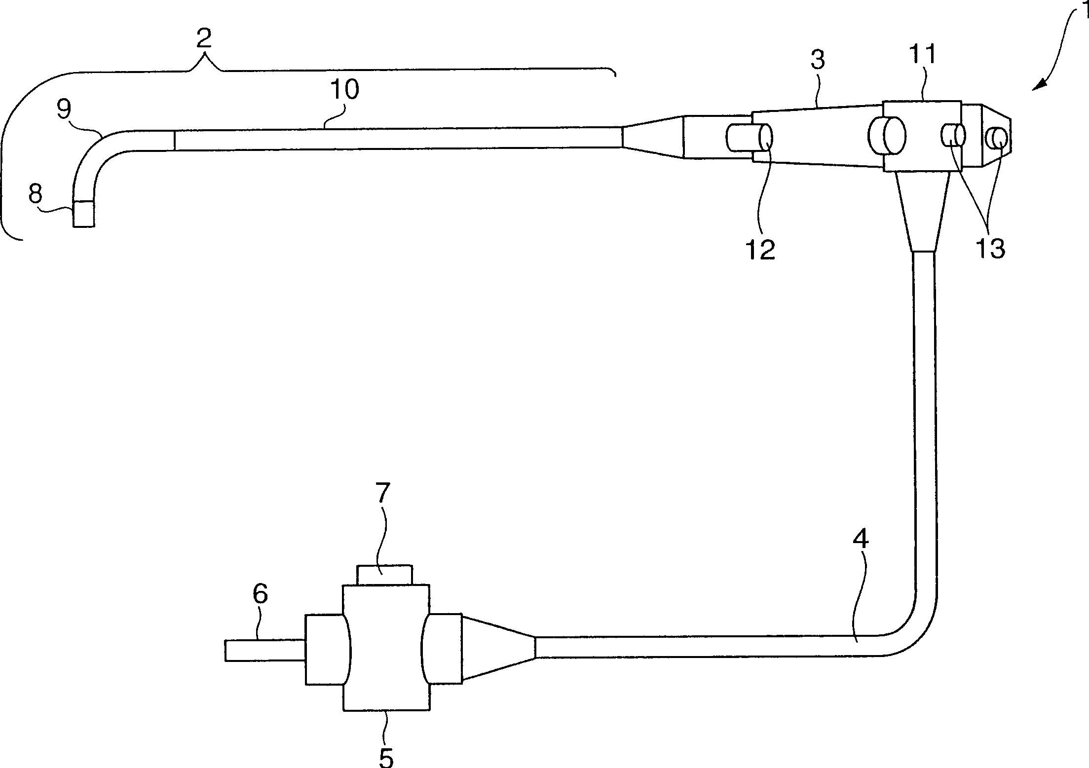
[0021] Such as figure 1 As shown, the endoscope 1 has: an insertion part 2, a solid-state imaging device such as a CCD is installed in its front end; an operation part 3 is connected to the base end side of the insertion part 2, and the observer holds it to perform various operations; The cord 4 extends from the operation part 3 .

[0022] A connector portion 5 is provided at an end portion of a universal cord (Unibar Salcode) 4 . A light guide connector 6, a camera connector 7, and the like are provided on the connector portion 5. As shown in FIG. The optical connector 6 and the camera connector 7 are connected to peripheral devices such as a light source device and a camera control unit.

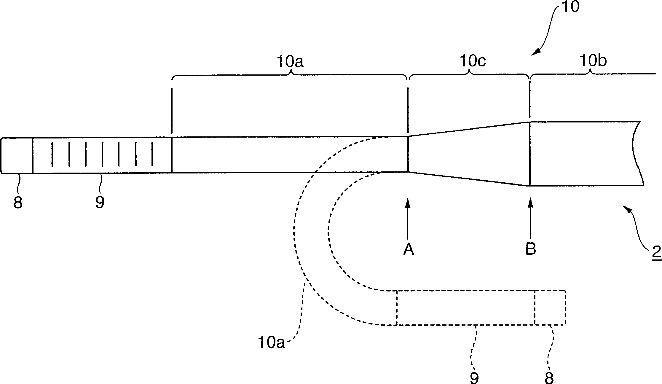
[0023] The insertion part 2 has, from the front end side, a front end part 8 , a freely bendable bending part 9 , and a flexible soft part 10 whose proximal end is connected to the operation part 3 ....

no. 2 Embodiment approach

[0060] Figure 8 The second embodiment of the present invention is shown. As shown in the figure, the endoscope device 41 shown in this embodiment includes a plurality of endoscopes 1A, 1B, and 1C having different functions, and can be commonly connected to the respective endoscopes 1A, 1B, and 1C. A light source device 42 , a video processor 43 , and a monitor 44 . Each of the endoscopes 1A, 1B, and 1C is used by selectively connecting a light source device 42 or a video processor 43 to a connector portion 5 provided on the distal end of a universal cord 4 extending from the operation portion thereof. In addition, although three types of endoscopes 1A, 1B, and 1C are shown in the figure, four or more types of endoscopes may be provided.

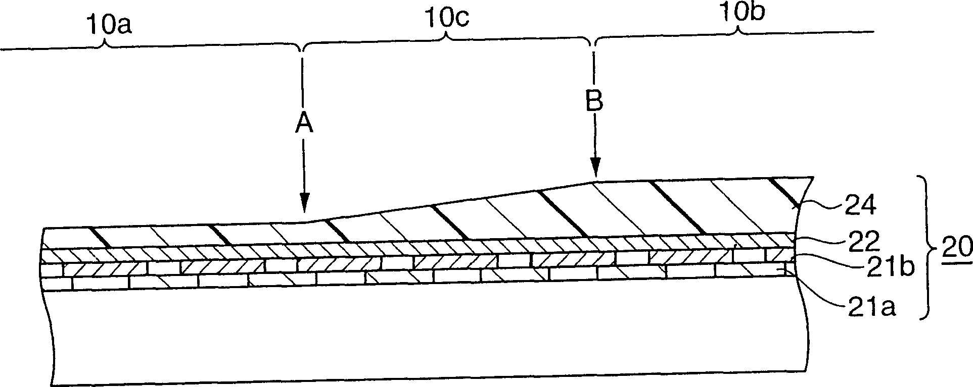
[0061] The first endoscope 1A has the same function as that of the endoscope 1 described in the previous embodiment, and the flexible part 10 is formed with a small-diameter part 10a, a large-diameter part 10b, and a 10b is connected to t...

no. 3 Embodiment approach

[0074] Figure 9 The third embodiment of the present invention is shown. In addition, since the shape of the insertion part is the same structure as the insertion part 2 demonstrated in 1st Embodiment, description here is abbreviate|omitted.

[0075] In this embodiment, at least one of between the front end portion 8 of the insertion portion 2 and the curved portion 9, and between the curved portion 9 and the small-diameter portion 10a provided on the front end side of the flexible portion 10, a Connecting part skins 48 and 49 for connecting various parts are provided. In addition, the figure shows the state where both connection part skins 48 and 49 are arrange|positioned. In addition, the connecting part sheaths 48 and 49 can be applied to various mechanisms such as hard tubular parts, adhesives, or flexible heat-shrinkable tubes.

[0076] In the endoscope of this embodiment, the outer diameter of the large-diameter portion 10b provided on the hand side of the flexible po...


PUM


Abstract

The present invention provides an endoscope, which has a front end portion (8), a freely bendable bending portion (9), and a flexible soft The part (10) is formed on the front end side of the soft part (10): a small diameter part (10a), a large diameter part (10b), and a connection between the small diameter part (10a) and the large diameter part (10b). The tapered portion (10c) in between, and at least a part of the tapered portion (10c) is arranged at a position more forward than 70 cm from the front end of the endoscope. When the insertion part (2) is inserted into the large intestine and its front end (8) is inserted into the cecum at the shortest distance, it is known that the distance from the anus to the front end of the front end (8) is generally about 60 to 70 cm. Therefore, good insertability can be obtained by disposing at least a part of the tapered portion (10c) more forward than 70 cm from the front end of the endoscope.

Description

technical field [0001] The present invention relates to an endoscope capable of improving insertability into the large intestine. Background technique [0002] Generally, an insertion portion of an endoscope is provided with a flexible soft portion, and the distal end of the flexible portion is connected to a distal end portion via a bending portion. On the front end surface of the front end portion, an observation window, an illumination window, an opening of a treatment instrument insertion channel, and the like are arranged as prescribed. [0003] It is well known that the soft part becomes easy to bend flexibly by increasing the flexibility of the portion near the distal end, while reducing the flexibility of the portion near the base end improves the insertion property. [0004] Therefore, for example, Japanese Patent Application Laid-Open No. 2001-190494 discloses a technique in which the flexibility ratio of the portion near the proximal end is increased by forming t...

Claims


Application Information

Patent Timeline
IPC IPC(8): A61B1/00A61B1/005A61B1/018A61B1/12A61B1/31H04N7/18
CPCA61B1/00071A61B1/0011A61B1/0052A61B1/0055A61B1/018A61B1/12A61B1/31H04N7/181A61B1/00078A61B1/005
Inventor 森山宏树
Owner OLYMPUS CORP
Why Eureka
Try Eureka