

Image forming method and image forming device
A technology of image and imaging conditions, applied in the direction of electric recording process applying charge pattern, equipment for applying electric recording process of charge pattern, electric recording technique, etc. Problems such as the increase in the charge amount, to achieve the effect of stable development, stable development, and effective increase in toner concentration
- Summary
- Abstract
- Description
- Claims
- Application Information
AI Technical Summary
Problems solved by technology
Method used
Image

Examples
Embodiment approach 1
[0127] Figure 4 It is a sectional view showing the image forming apparatus according to Embodiment 1 of the present invention.
[0128] This image forming apparatus has: a photosensitive drum 1, a charging device 2, an exposure device 3, a developing device 4, a transfer device 5, a paper feeding unit 6, a fixing device 7, a toner cartridge 8, a cleaning device 9, an ATC sensor 10, a humidity sensor 11 and photoelectric sensor 12.
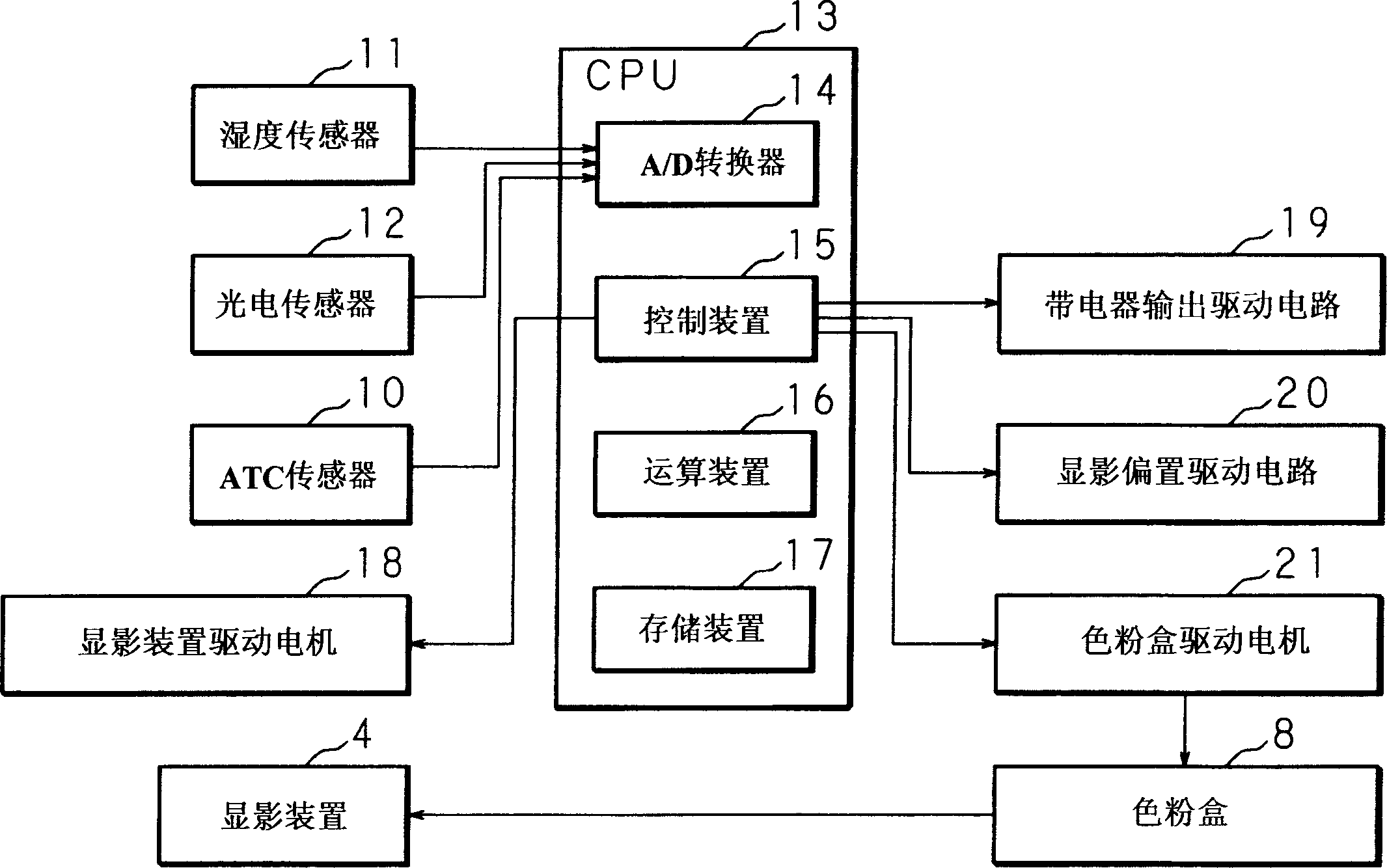
[0129] Figure 5 It is a block diagram showing the configuration of the image forming apparatus according to Embodiment 1 of the present invention.
[0130] The CPU 13 that constitutes the control section has: the A / D converter 14 that converts the analog output voltage value of the ATC sensor (toner concentration sensor) 10, the humidity sensor 11, and the photoelectric sensor 12 into a digital output voltage value; ; a developing bias driving circuit 20; a control device 15 for controlling the developing device driving motor 18 and the toner ...
Embodiment approach 2
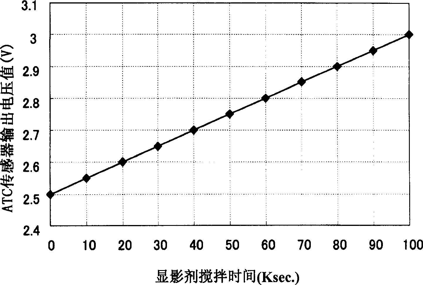
[0215] Depending on the frequency of use of the device by the user for copying or printing, the developer stirring stress per predetermined time varies. This difference in the stirring stress of the developer per predetermined unit time causes a difference in the charge amount of the toner. As a result, although the toner concentration is the same, the output voltage value of the ATC sensor 10 is different, and the stirring stress per unit time is lower. In the developer with a small device usage frequency, the toner concentration increases and the charge amount decreases, causing toner scattering, toner adhesion to areas without images, or image damage, resulting in lower image quality. Conversely, in a developer with a high stirring stress per unit time and a device usage frequency, the toner density decreases, the charge amount increases, and the image density decreases, such as blurring of characters, resulting in a decrease in image quality.
[0216] According to the pres...
Embodiment approach 3
[0244] Figure 20 ~ Figure 22 It is a flowchart showing the correction processing procedure of the reference output voltage value based on the change in humidity and the frequency of use of the device by the control device 15 according to the third embodiment.
[0245] When starting up by turning on the power or the like, first, the CPU 13 of the image forming apparatus judges whether or not it is time to implement process control (step S51 ). The execution timing of the process control is a timing that requires control, such as when the power is turned on, after a predetermined time has elapsed since the power is turned on, or after a predetermined number of copies has been completed.
[0246] In step S51, when it is judged that it is not the execution time of the process control, the normal copying operation is repeated until the execution time (step S52).
[0247] In step S51, when it is determined that it is time to implement process control, charging, exposure, and devel...
PUM
 Abstract
Description
Claims
Application Information