Piezo actuator driving circuit

一种压电致动器、驱动电路的技术,应用在压电效应/电致伸缩或磁致伸缩的电动机、发电机/电动机、电气元件等方向,能够解决不能正常工作、压电致动器不能被驱动等问题

一种压电致动器、驱动电路的技术,应用在压电效应/电致伸缩或磁致伸缩的电动机、发电机/电动机、电气元件等方向,能够解决不能正常工作、压电致动器不能被驱动等问题

CN1897443AInactive Publication Date: 2007-01-17SAMSUNG ELECTRO MECHANICS CO LTD

Image

  • Piezo actuator driving circuit
  • Piezo actuator driving circuit
  • Piezo actuator driving circuit

Examples


Embodiment Construction

[0048] Reference will now be made in detail to embodiments of the present general inventive concept, examples of which are illustrated in the accompanying drawings, wherein like reference numerals refer to like elements throughout. The embodiments are described below in order to explain the present general inventive concept by referring to the figures.

[0049] Hereinafter, preferred embodiments of the present invention will be described in detail with reference to the accompanying drawings.

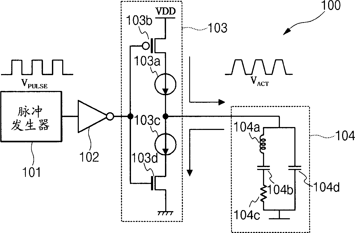
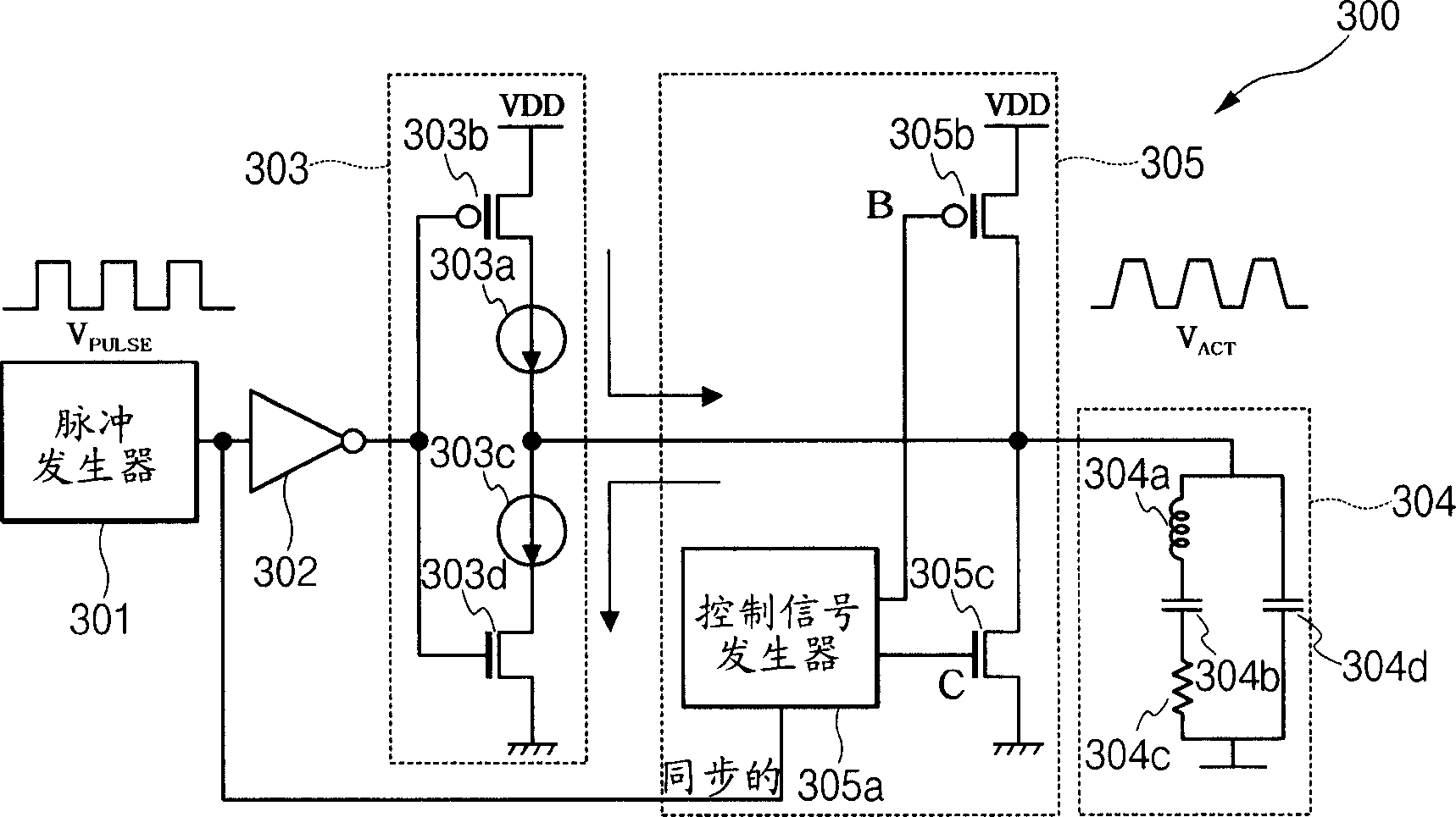
[0050] image 3 is a circuit diagram showing a piezoelectric actuator driving circuit 300 according to the present invention. Such as image 3 As shown, the piezoelectric actuator driving circuit 300 includes: a pulse generator 310, which generates a first voltage pulse V with a constant period PULSE ; The first excitation stage 302 receives the first pulse V of the pulse generator 301 PULSE , and buffer the first voltage pulse V PULSE In order to output; the second excitation stage...


PUM


Abstract

The present invention relates to a piezo actuator driving circuit. The piezo actuator driving circuit includes a pulse generator that generates a first voltage pulse with a constant period; a first driver stage that receives the first voltage pulse of the pulse generator and buffers the first voltage pulse to output; a second driver stage that converts the first voltage pulse, buffered and output in the first driver stage, into a first current pulse to output; a driving voltage maintaining section that is connected to the pulse generator and the second driver stage so as to output a second current pulse for maintaining a constant amplitude of driving voltage pulse; and a piezo actuator that is connected to the second driver stage and the driving voltage maintaining section so as to be charged and discharged by the first and second current pulses and that is driven by the driving voltage pulse with a constant amplitude.

Description

[0001] Related Application Cross Reference [0002] This application claims priority from Korean Patent Application No. 2005-0062052 filed with the Korean Industrial Property Office on Jul. 11, 2005, the disclosures of which are incorporated herein by reference. technical field [0003] The present invention relates to a piezoelectric actuator driving circuit, and more particularly, to a piezoelectric actuator driving circuit capable of preventing signal distortion caused by processing deviation or temperature variation when manufacturing a piezoelectric actuator , and it is possible to maintain the driving voltage by additionally transmitting current pulses to the driving voltage holding portion of the piezoelectric actuator to prevent the piezoelectric actuator from malfunctioning or stopping. Background technique [0004] At present, the mobile phone market is growing rapidly at a rate of more than 20% every year. Recently, there has been a demand for the development of ...

Claims


Application Information

Patent Timeline
17 Jan 2007
Publication
CN1897443A
IPC
H02N2/00; H02N2/06; H02N2/14; H10N30/20
CPC
H02N2/0075; H02N2/06
Inventors
闵丙雲; 河昌佑