

Stapler
A stapler and staple technology, which is applied in the directions of staple staple tools, staple tools, manufacturing tools, etc., can solve the problem that the bent shape of the staple feet cannot be maintained stable, and the length of the movable pliers cannot be formed to a large extent. , poor cutting, etc.
- Summary
- Abstract
- Description
- Claims
- Application Information
AI Technical Summary
Problems solved by technology
Method used
Image

Examples
Embodiment 1
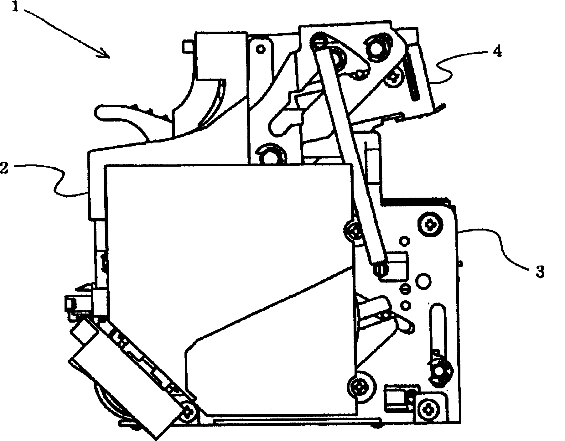
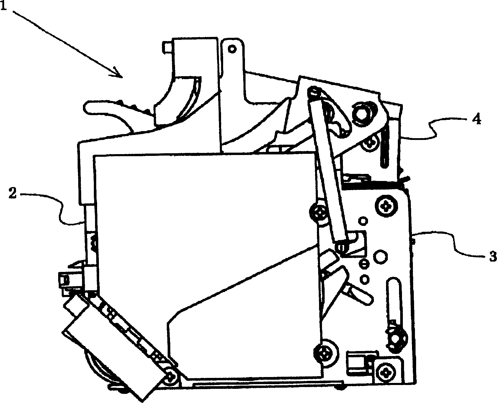
[0037] figure 1 A stapler showing an embodiment of the present invention. A motor and a driving mechanism for rotating and driving by the motor are accommodated in the machine frame 2 forming the outline of the stapler 1, and a drive-in mechanism part 3 is formed at the bottom of the machine frame 2, and the drive-in mechanism part 3. Driven by the above-mentioned driving mechanism, the staples formed in a U-shape are driven out to the binding paper. The driving mechanism part 3 of the stapler 1 of this embodiment forms a plurality of linear staple materials connected to each other into a U-shaped staple by a forming device, and the formed staple is formed by a driving device. The paper is driven upward toward the binding paper arranged above the driving mechanism unit 3 .
[0038] Furthermore, a clincher mechanism part 4 is formed on the upper part of the machine frame 2 opposite to the above-mentioned driving mechanism part 3, and the clincher mechanism part 4 makes the st...
PUM
 Abstract
Description
Claims
Application Information