Heat tube radiating device

A heat dissipation device and heat pipe technology, which is applied in cooling/ventilation/heating transformation, instrument cooling, instrument and other directions, can solve the problems of high heat density, small air flow, low heat distribution of radiators, etc., and achieve large heat distribution area, Improved heat exchange rate and improved heat dissipation performance

Inactive Publication Date: 2007-03-21
FU ZHUN PRECISION IND SHENZHEN +1
View PDF1 Cites 3 Cited by
  • Summary
  • Abstract
  • Description
  • Claims
  • Application Information

AI Technical Summary

Problems solved by technology

However, the heat of this sunflower-shaped radiator is mainly concentrated in the cylinder and the fin root near the cylinder, where the area is small and the heat density is high, and the heat distribution of the entire radiator gradually decreases from the circumference of the cylinder to the outside. The heat at the end of the fins of the body is less, while the air flow of the axial fan gradually increases from the central part to the peripheral direction, so that the strong air flow of the fan corresponds to the lower part of the heat distribution of the radiator, while the weak air flow of the fan corresponds to It is the part of the heat sink with a small area and high heat density. The cooperation between the fan and the heat sink is obviously not corresponding, and the forced heat exchange effect of the fan cannot be fully utilized.
In addition, due to the airflow loss caused by the column part of the radiator and the flow inertia of the fan airflow, the airflow gradually spreads outward from top to bottom and away from the column, and the air flow of the higher temperature part of the radiator near the heat source Small, ultimately affecting the heat dissipation efficiency of the heat sink

Method used


Image

  • Heat tube radiating device
  • Heat tube radiating device
  • Heat tube radiating device

Examples


Embodiment Construction

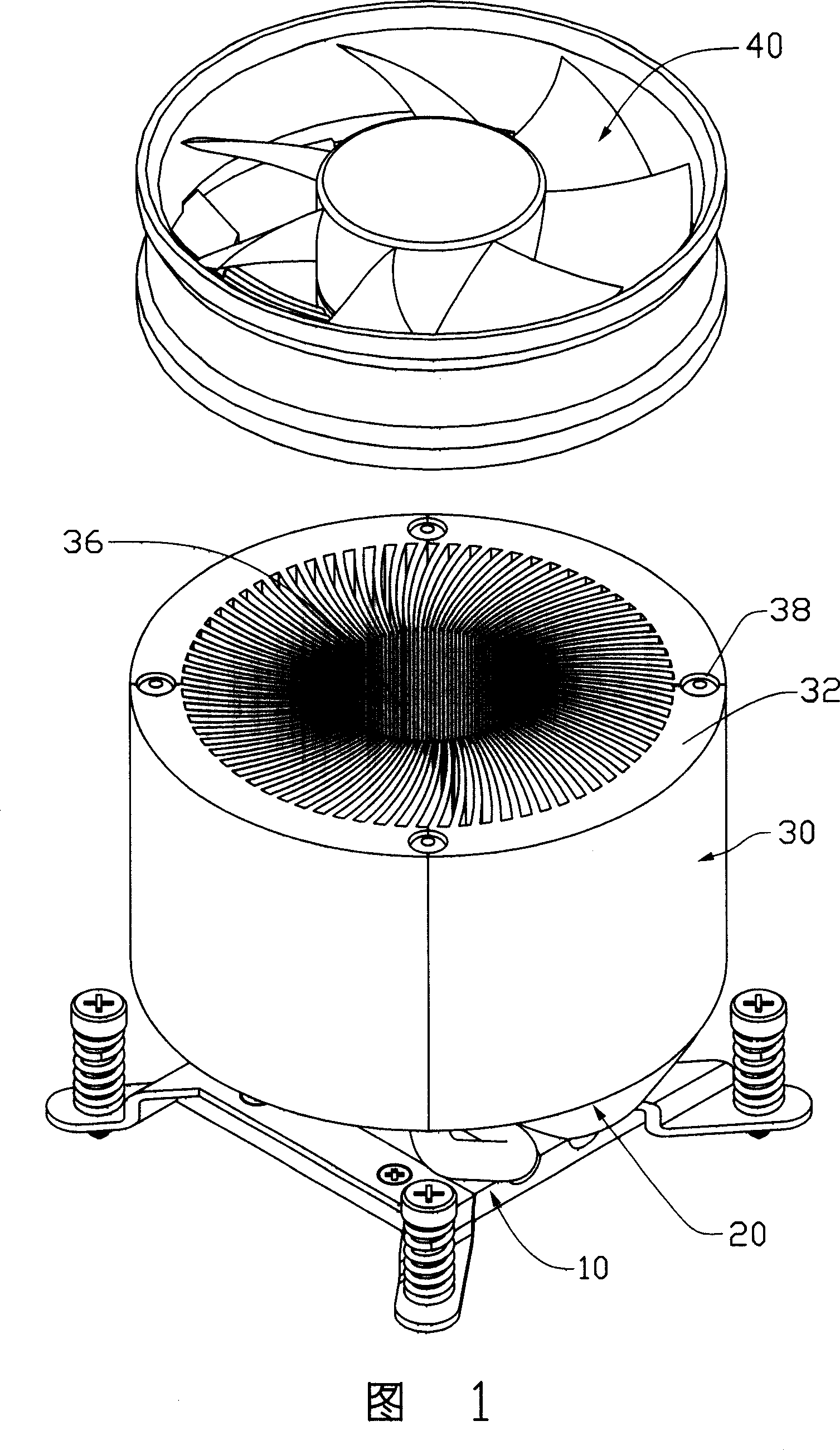
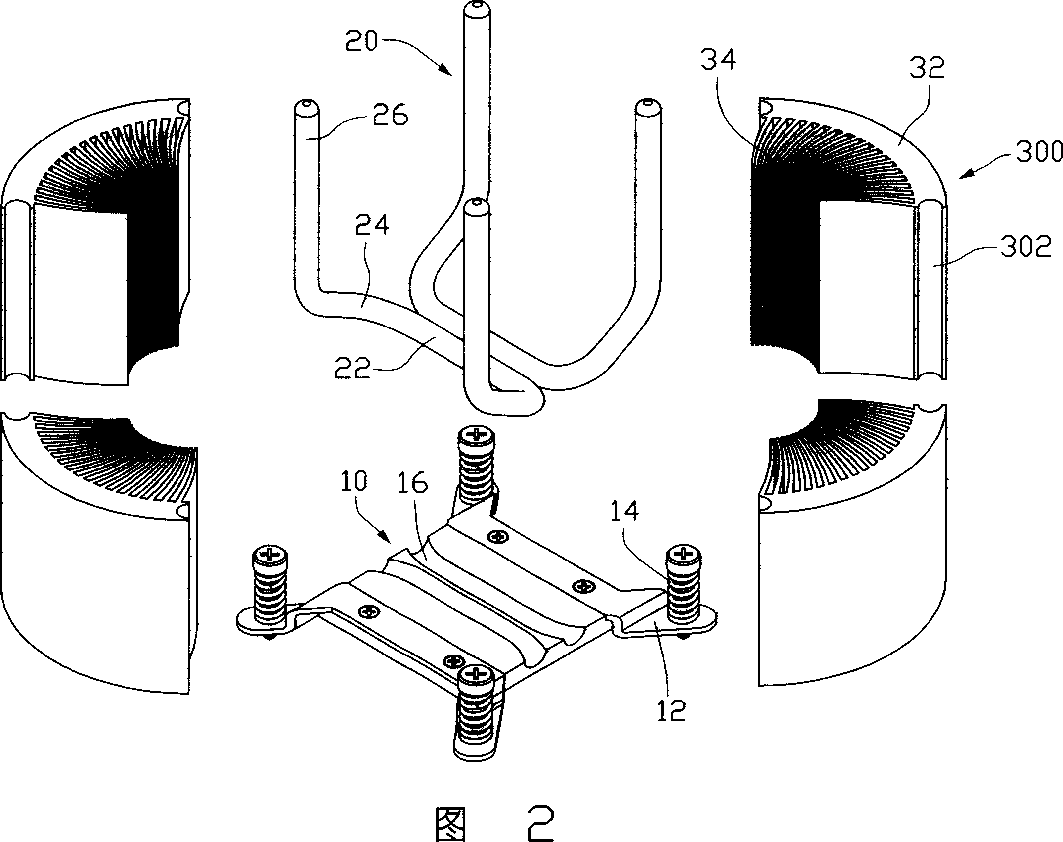
[0014] The heat pipe heat dissipation device of the present invention is used to install on heat-generating electronic components such as a central processing unit (not shown in the figure) to dissipate heat. Please refer to Fig. 1 and Fig. 2, the first embodiment of the heat pipe cooling device of the present invention comprises a substrate 10, two heat pipes 20 which are attached to the substrate 10 and whose two ends extend vertically upwards, and a cylindrical tube connected to the heat pipe 20 Radiator 30.

[0015] The base plate 10 is roughly rectangular, and its four corners are provided with fixing feet 12. Screws and springs are pre-assembled on the fixing feet 12 to fix the fixing piece 14 with a cooling device. The two grooves 16 are substantially parallel.

[0016] The heat pipe 20 is roughly three-dimensional U-shaped, which has an evaporation portion 22 accommodated in the groove 16 of the substrate 10, an inclined portion 24 extending obliquely outward and upwa...


PUM


Abstract

A heat radiating device of heat pipe consists of base plat, heat pipe and heat radiating body. It is featured as connecting heat pipe with base plate and connecting heat pipe with heat radiating body, forming heat radiating body by a heat conductive cylinder wall and a number of fin plates being used to radiate heat and being extended out from internal surface of said cylinder wall then connecting heat pipe with heat conductive cylinder wall.

Description

【Technical field】 [0001] The invention relates to a heat dissipation device, in particular to a heat pipe heat dissipation device installed on an electronic component for heat dissipation. 【Background technique】 [0002] With the continuous development of the electronic industry, the operating speed and overall performance of electronic components (especially the central processing unit) are constantly improving. However, its calorific value has also increased. On the other hand, its volume has become smaller and smaller, and its heat generation has become more concentrated. This has made it impossible for the industry to use heat dissipation devices that only use metal entities for heat dissipation to meet the heat dissipation requirements of high-end electronic components. [0003] For this reason, the industry has begun to use heat sinks with elements (such as heat pipes or boiling structures) that rely on the principle of phase change to transfer heat. The heat pipe is ...

Claims


Application Information

Patent Timeline
Patent Type & Authority Applications(China)
IPC IPC(8): H05K7/20G12B15/00H01L23/36G06F1/20
CPCH01L23/4006H01L23/467H01L23/427H01L2924/0002H01L2924/00
Inventor 邓根平吴宜强
Owner FU ZHUN PRECISION IND SHENZHEN
Why Eureka
Try Eureka