Switch device for switching multi-pole circuit

A switching device and circuit technology, applied in the direction of electrical switches, circuits, relays, etc., can solve the problems that are difficult to achieve, do not mention dual power conversion, processing and manufacturing, assembly level and material requirements, etc. The effect of reducing workload and points of failure

Active Publication Date: 2010-04-07
SHANGHAI ELECTRICAL APPLIANCES RES INSTGROUP +2
View PDF2 Cites 1 Cited by
  • Summary
  • Abstract
  • Description
  • Claims
  • Application Information

AI Technical Summary

Problems solved by technology

[0008] However, the above-mentioned patent does not mention dual power conversion, and this structure has high requirements on processing and manufacturing, assembly level and materials, which is labor-intensive and time-consuming, and it is difficult to realize based on the existing processing and manufacturing level in China.

Method used


Image

  • Switch device for switching multi-pole circuit
  • Switch device for switching multi-pole circuit
  • Switch device for switching multi-pole circuit

Examples


Embodiment Construction

[0022] ( figure 2 In , the switch device for switching multi-pole circuits is represented by Z, and the switch device that can switch the main circuit used in conjunction with switch device Z for switching multi-pole circuits is represented by C, and C can be a contactor (CTT) or control and protection Switching appliances (CPS).

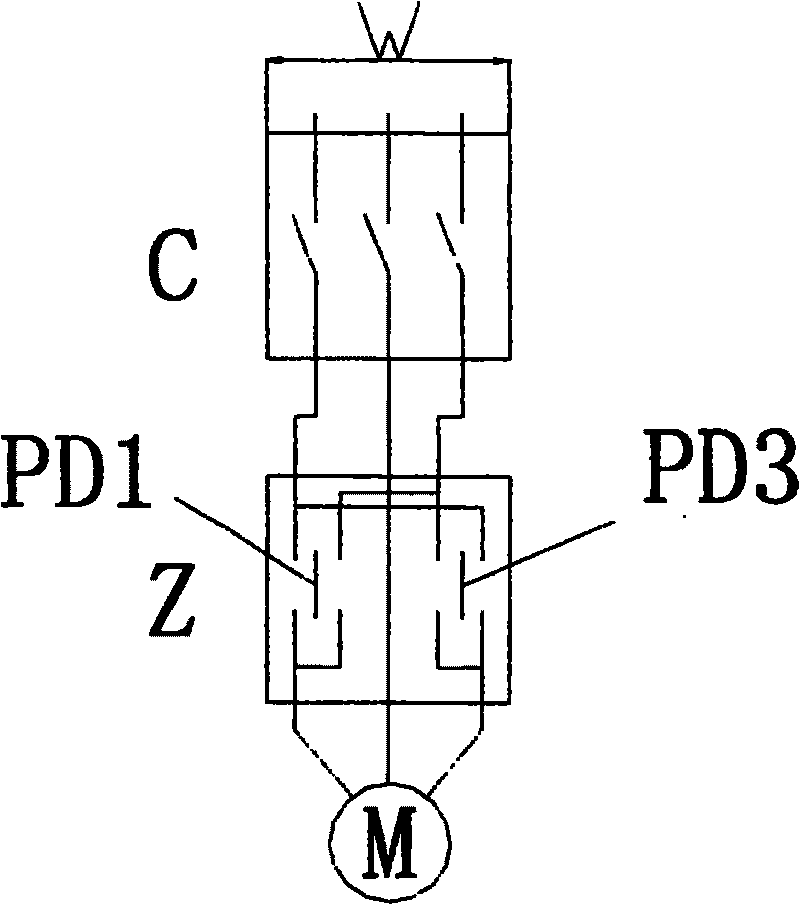
[0023] image 3 Among them, is the circuit diagram of the star-delta control implementation of the present invention.

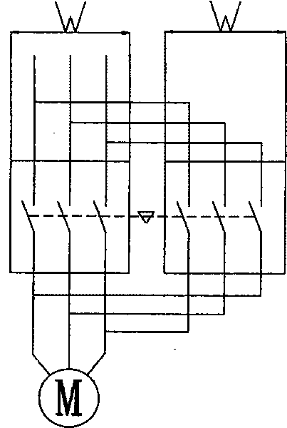
[0024] Figure 4 Among them, is the circuit diagram of the implementation of the two-speed control (two motors with different rotating speeds) of the present invention.

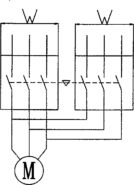
[0025] Figure 5 , is a circuit diagram of the implementation of the dual power conversion function of the present invention.

[0026] Such as Figure 6 As shown, the switching device Z mainly includes the conversion contacts and their conductive circuits P1, P2, P3, the printed circuit board PCB and the electromagnetic system EM, wherein the conversion con...


PUM


Abstract

This invention relates to one switch multi-electrode circuit device, which comprises one switch parts and is characterized by the following: matching the switch host circuit switch parts with triggerprobe changed into two different circuits through two positions to realize motor reverse, double direction, star angle, double power conversion or double speed operation control; conversion probe andcontrol electromagnetic iron and its control circuit distributed along the switch device and its matched switch to reduce switch device size. The switch device comprises conversion probe and its conductive loop, print circuit board and cable system.

Description

Technical field: [0001] The invention relates to a switch device for switching a multi-pole circuit, more precisely relates to a switch device used for a multi-pole switching device, and belongs to the field of electric technology. Background technique: [0002] At present, the reversible, two-way, star-delta or two-speed control of motors at home and abroad often adopts at least two control and protection switchgears, two contactors or two other switchgears with electrical interlock and mechanical interlock. achieve, see Figure 1a shown. [0003] This type is also often used for dual-power conversion switching appliances composed of separate devices, that is, two control and protection switching appliances, two contactors or two circuit breakers are implemented by adding electrical interlocks and mechanical interlocks, see Figure 1b shown. [0004] For example, patent ZL 01238478.X discloses a switching device for controlling and protecting a motor, which can realize re...

Claims


Application Information

Patent Timeline
Patent Type & Authority Patents(China)
IPC IPC(8): H01H19/38H01H47/00H01H50/00H02P1/02
Inventor 曾萍贾峰宋伟宏
Owner SHANGHAI ELECTRICAL APPLIANCES RES INSTGROUP
Why Eureka
Try Eureka