Zip line apparatus

a technology of zip line and apparatus, which is applied in the field of trolleys, can solve the problems of no seat no handle for zip line systems, and user's little or no ability to slow down or even stop, and achieve the effect of facilitating the construction and suspension of cables

Inactive Publication Date: 2018-07-17
NORTH STAY LLC
View PDF27 Cites 8 Cited by
  • Summary
  • Abstract
  • Description
  • Claims
  • Application Information

AI Technical Summary

Benefits of technology

[0007]The zip line system of the present invention may be offered as a completely assembled unit or a kit with various components including for example the trolley, a braking system, handle, webbing, a seat and a trolley return line. Other components of the system could include but are not limited to a safety harness, a cable assembly system as well as structural accessories, fasteners and tools such as a come-along and cable cutters which facilitate constructing and suspending the cable between two points. The come-along or ratchet provides for installation, adjustment and removal of the cable in a relative short amount of time making the zip line system portable for installation in remote locations.
[0008]The zip line kit has an improved trolley system that supports at least one, and preferably two or more wheels or pulleys sandwiched between two frame pieces. The frame pieces can be manufactured of aluminum or other metal, certain rigid plastics or other stiff durable materials such as carbon fiber could be used as well. The frames are affixed to one another sandwiching the wheels therebetween. The frames can be removably affixed for instance by bolts, screws or other such fastening devices. The frames can be permanently connected for instance by rivets or welding or even hingedly connected by a hinge or quick-release and fastening system which allows the frames to hinge along parallel or non-parallel planes with respect to one another. Such a hinge connection may facilitate taking the trolley on and off a cable without having to take the cable down or completely take the trolley apart.

Problems solved by technology

Known zip line systems do not have a seat to comfortably support the rider during the traverse, nor an adjustment mechanism which makes the seat easily adjustable for people of different sizes.
Known zip line systems also generally do not have any type of handle for a rider to hold directly onto the trolley while they are also supported by the adjustable seat.
Additionally, known zip line systems do not have any type of braking system in the trolley itself and the user has little or no ability to slow themselves down, or even stop themselves during the traverse.

Method used


Image

  • Zip line apparatus
  • Zip line apparatus
  • Zip line apparatus

Examples


Embodiment Construction

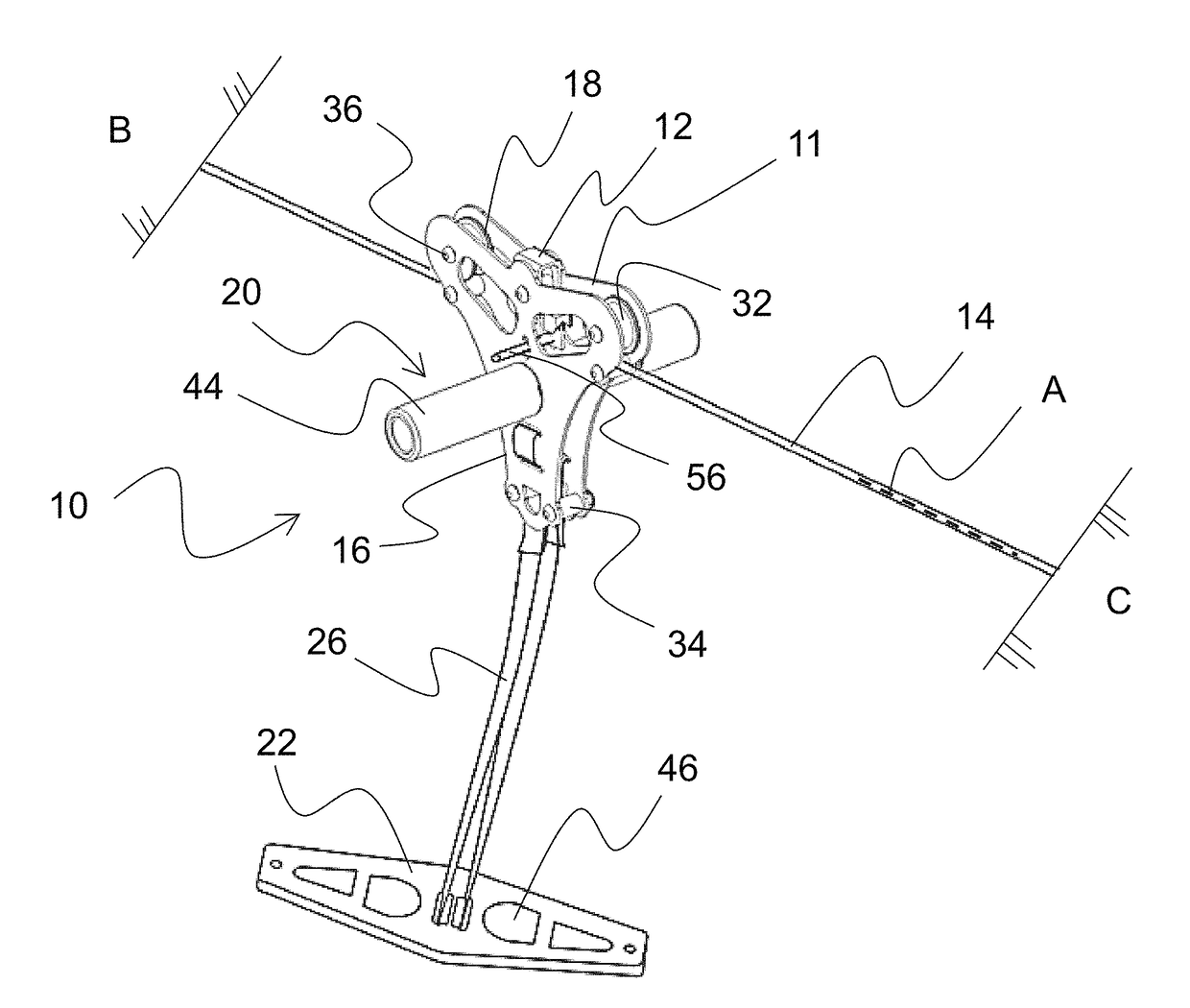
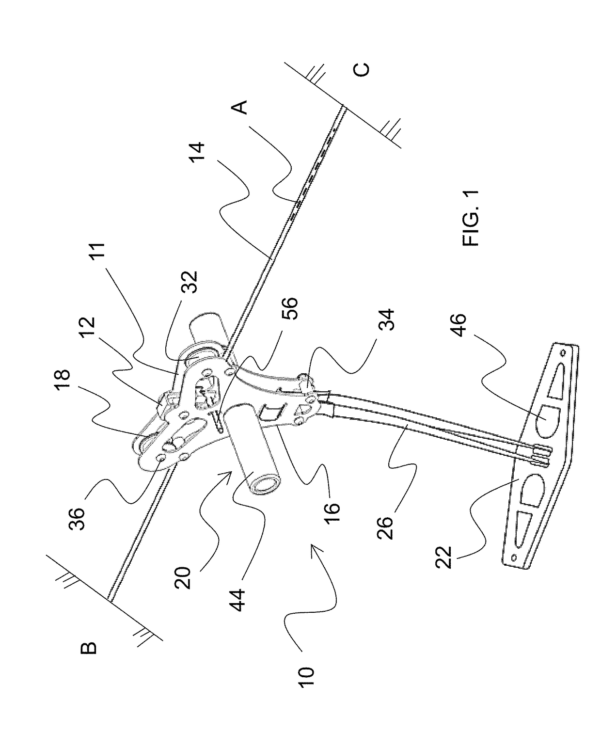
[0079]Embodiments of the present invention relate to a trolley for guiding a person or an object using gravity along an extended cable line suspended between two spaced apart objects such as trees or towers, and more specifically relates to a zip line kit or system with an easily adjustable seat and handle arrangement which in combination with a wheel and braking system for the device facilitates a safe and controllable descent along the cable line. The trolley is provided with at least two wheels spaced apart at a suitable distance to increase ride smoothness, provide sufficient space to accommodate the braking system and improve operation of the zip line system along the extended cable.

[0080]FIG. 1 shows in general a zip line system 10 of the present invention including a trolley 11 with a braking system 12 supported on an extended cable 14. The trolley 11 comprises two frame pieces 16 that house one or more wheels 18 for engaging the cable 14. The cable is understood to be in one...


PUM

PropertyMeasurementUnit
lengthaaaaaaaaaa
distanceaaaaaaaaaa
distanceaaaaaaaaaa

Abstract

Embodiments of the present invention generally relate to a zip line or trolley system kit for propelling a person or an object using gravity along an extended cable line suspended between two trees or towers. The zip line or trolley system may include an easily installable support harness assembly, a braking system and a removable seat fixture to provide for the zip line system to be completely portable to be carried, installed and taken down in remote locations.

Description

CROSS-REFERENCE TO RELATED APPLICATIONS[0001]This application is a continuation-in-part of U.S. patent application Ser. No. 12 / 879,700, filed Sep. 10, 2010, entitled “ZIP LINE APPARATUS” and claims priority to U.S. provisional patent application Ser. No. 61 / 320,668, filed Apr. 2, 2010, entitled “ZIP LINE KIT” the disclosures of which are incorporated by reference herein in their entireties.FIELD OF THE INVENTION[0002]The invention relates to a trolley for guiding a person or an object using gravity along an extended cable line suspended between two spaced apart objects such as trees or towers, and more specifically relates to a zip line kit or system with an easily adjustable and removable seat and handle arrangement which in combination with a wheel and braking system for the device facilitates a safe and controllable descent along the cable line. The trolley is provided with at least two wheels spaced apart at a suitable distance to increase ride smoothness, provide sufficient spa...

Claims


Application Information

Patent Timeline
Patent Type & Authority Patents(United States)
IPC IPC(8): B61H1/00A63G21/22B61B12/02A62B35/00
CPCB61H1/00A63G21/22B61B12/02Y10T29/49826A62B35/0081
Inventor BROWN, STEPHEN DOUGLAS
Owner NORTH STAY LLC
Why Eureka
Try Eureka