Zip line apparatus

a technology of zip line and apparatus, which is applied in the field of trolleys, can solve the problems of no seat for zip line systems, no handle for users, and no known zip line systems, and achieve the effects of convenient seat adjustment, convenient transportation, and convenient transportation

Inactive Publication Date: 2011-10-06
NORTH STAY LLC
View PDF3 Cites 40 Cited by
  • Summary
  • Abstract
  • Description
  • Claims
  • Application Information

AI Technical Summary

Benefits of technology

[0006]The zip line system of the present invention may be offered as a completely assembled unit or a kit with various components including for example the trolley, a braking system, handle, webbing, a seat and a trolley return line. Other components of the system could include but are not limited to a safety harness, a cable as well as structural accessories, fasteners and tools such as a come-along and cable cutters which facilitate constructing and suspending the cable between two points.
[0007]The zip line kit has an improved trolley system that supports at least one, and preferably two or more wheels sandwiched between two frame pieces. The frame pieces can be manufactured of aluminum or other metal, certain rigid plastics or other stiff durable materials such as carbon fiber could be used as well. The frames are affixed to one another sandwiching the wheels therebetween. The frames can be removably affixed for instance by bolts, screws or other such fastening devices. The frames can be permanently connected for instance by rivets or welding or even hingedly connected by a hinge or quick-release and fastening system which allows the frames to hinge along parallel or non-parallel planes with respect to one another. Such a hinge connection may facilitate taking the trolley on and off a cable without having to take the cable down or completely take the trolley apart.

Problems solved by technology

Known zip line systems do not have a seat to comfortably support the rider during the traverse, nor an adjustment mechanism which makes the seat easily adjustable for people of different sizes.
Known zip line systems also generally do not have any type of handle for a rider to hold directly onto the trolley while they are also supported by the adjustable seat.
Additionally, known zip line systems do not have any type of braking system in the trolley itself and the user has little or no ability to slow themselves down, or even stop themselves during the traverse.

Method used


Image

  • Zip line apparatus
  • Zip line apparatus
  • Zip line apparatus

Examples


Embodiment Construction

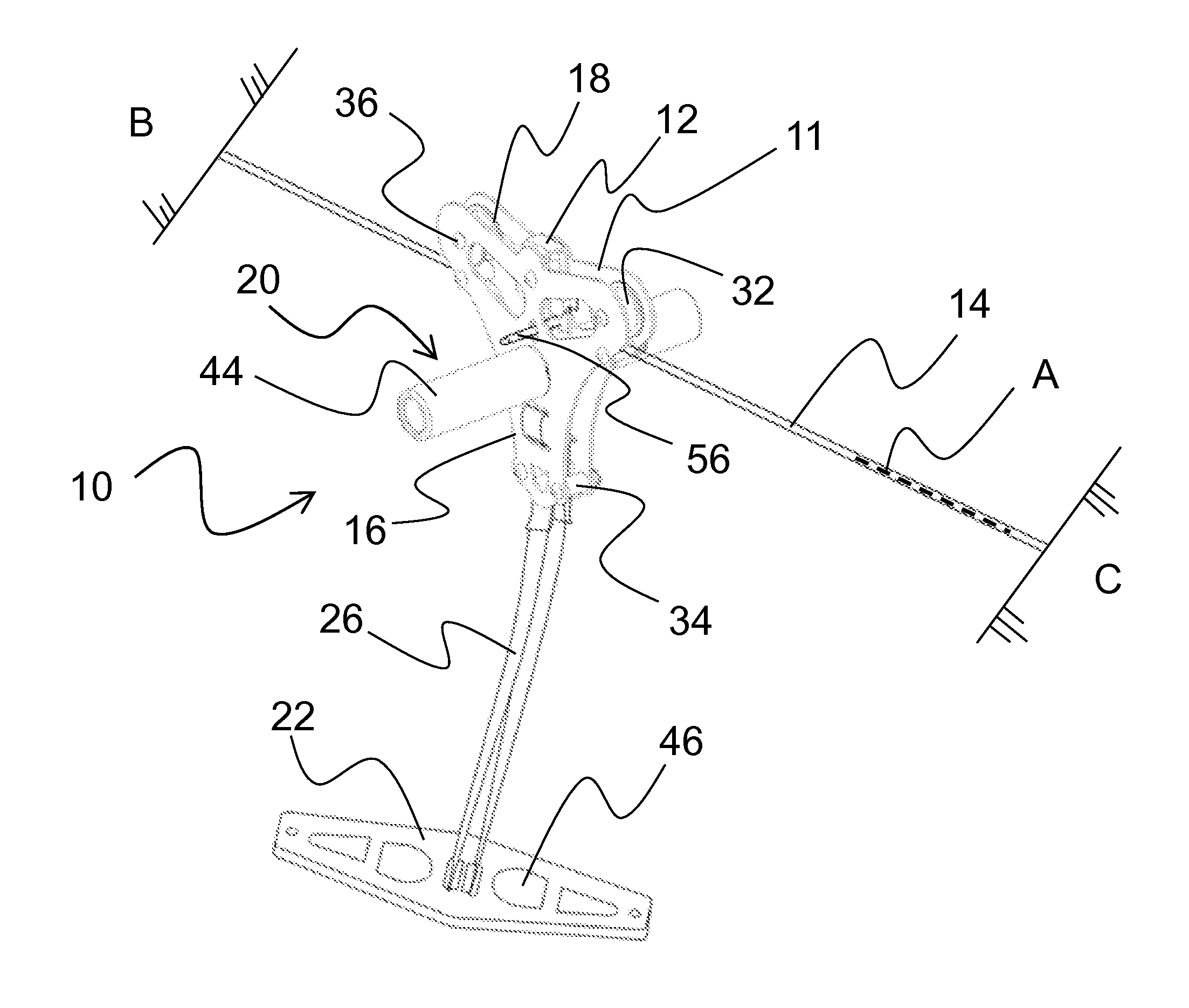
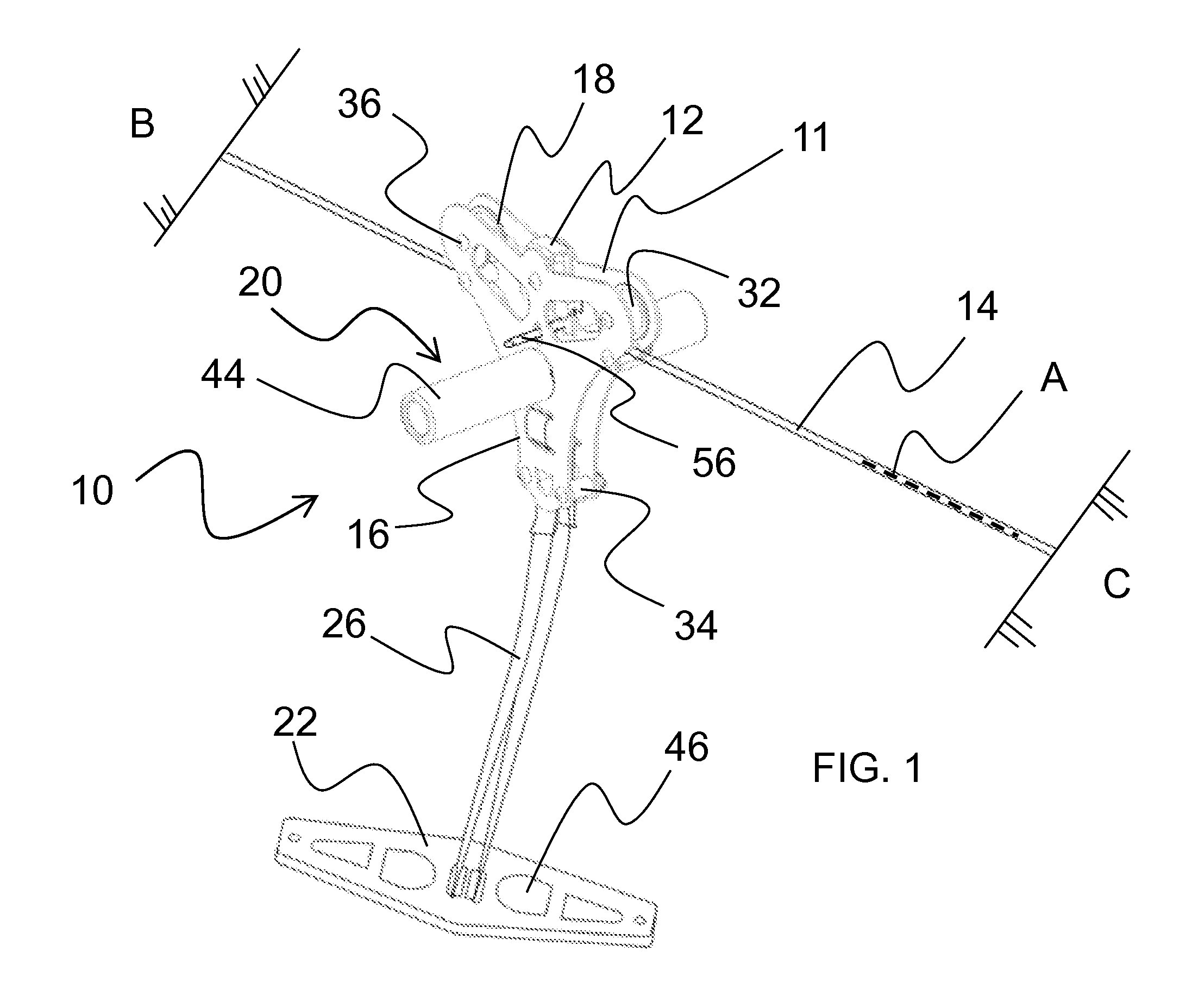
[0035]FIG. 1 shows in general a zip line apparatus 10 of the present invention including a trolley 11 with a braking system 12 supported on an extended cable 14. The trolley 11 comprises two frame pieces 16 that house one or more wheels 18 for engaging the cable 14. The cable is understood to be in one embodiment an extended steel cable, but could alternatively be a rope, line, rail or wire, but for purposes of description is hereinafter referred to as cable 14. The cable is fastened at either end between two spaced apart points B-C to generally define a longitudinal travel axis A for the trolley. The trolley 11 may also include a braking system 12, handle 20, a seat 22 and an adjustment mechanism 26 facilitating changing the spacing between the seat 22 and the trolley 11.

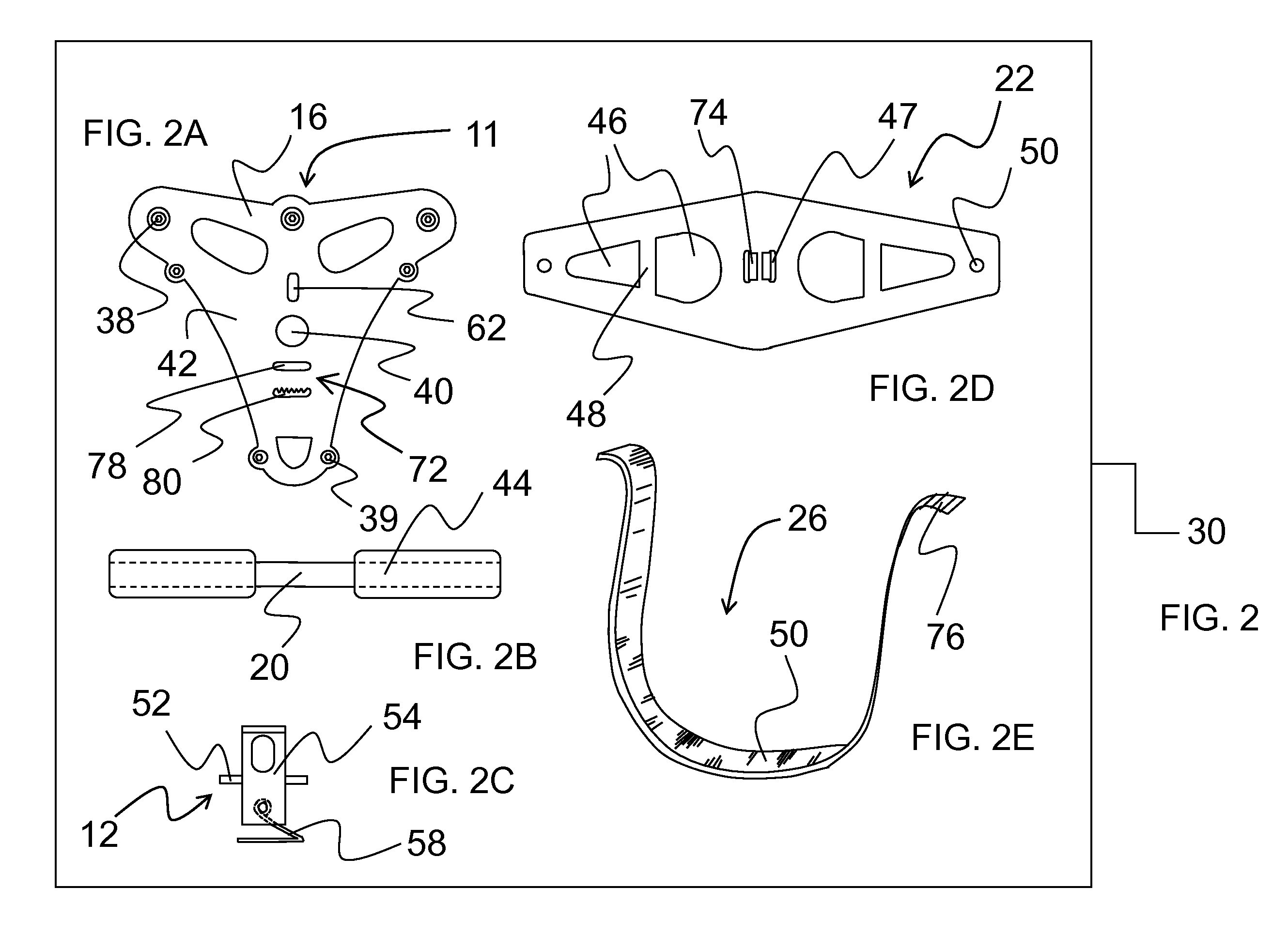
[0036]A basic zip line kit 30 is shown in FIG. 2 and the components of the kit 30 are shown in FIGS. 2A-2E comprising the trolley 11, handle 20, braking system 12, seat 22, and adjustment mechanism 26, respectfully...


PUM

PropertyMeasurementUnit
distanceaaaaaaaaaa
lengthaaaaaaaaaa
distanceaaaaaaaaaa

Abstract

A zip line or trolley system kit for propelling a person or an object using gravity along an extended cable line suspended between two trees or towers. The zip line system having a frame with one or more wheels, an adjustable length seat, a handle and a braking system for slowing the speed of descent of the zip line system. The trolley system having at least two wheels spaced apart at a suitable distance to increase ride smoothness and improve sliding of the zip line system along the extended cable. An actuator of the braking system allows for the rider to control of the speed of descent of the zip line system.

Description

FIELD OF THE INVENTION[0001]The invention relates to a trolley for guiding a person or an object using gravity along an extended cable line suspended between two spaced apart objects such as trees or towers, and more specifically relates to a zip line kit or system with an easily adjustable seat and handle arrangement which in combination with a wheel and braking system for the device facilitates a safe and controllable descent along the cable line. The trolley is provided with at least two wheels spaced apart at a suitable distance to increase ride smoothness, provide sufficient space to accommodate the braking system and improve operation of the zip line system along the extended cable.BACKGROUND OF THE INVENTION[0002]A zip line system is a work or recreational device which allows a user to maneuver or traverse themselves, or another person, object or load by use of a trolley along a suspended line or cable generally from a higher point of elevation to a lower point of elevation u...

Claims


Application Information

Patent Timeline
Patent Type & Authority Applications(United States)
IPC IPC(8): B61D15/00B61B3/00B23P11/00
CPCA63G21/20Y10T29/49826B61B12/02A63G21/22
Inventor BROWN, STEPHEN DOUGLAS
Owner NORTH STAY LLC
Why Eureka
Try Eureka