Method and measuring apparatus for determining specific quantities for gas quality

a technology of specific quantities and measuring apparatus, which is applied in the direction of instruments, specific gravity measurement, liquid/fluent solid measurement, etc., can solve the problems of not being able to draw conclusions with sufficient calorific value precision, and only suitable methods, so as to achieve precise values, correlation of precision, and higher precision in the determination of calorific value and energy

Active Publication Date: 2018-10-16
MEMS
View PDF9 Cites 6 Cited by
  • Summary
  • Abstract
  • Description
  • Claims
  • Application Information

AI Technical Summary

Benefits of technology

[0018]In combination with a microthermal sensor as described in the patent application EP 14001767, it is possible to omit the critical nozzle due to the information on the sound velocity, because the latter also supplies the sound velocity in first order, with the advantage that no critical pressure conditions are necessary, i.e. it is possible to measure at given pressure. Consequently, neither compressors nor vacuum pumps are required in low-pressure gas networks.
[0075]Inclusion of the thermal conductivity λTi measured with the microthermal sensor (at one or several temperatures Ti) to further improve the correlation of the standard density ρnorm.
[0105]The method and the measuring apparatus according to the present invention for determining specific quantities for the gas quality or the energy consumption offer the advantage that they can also be used in low-pressure gas networks without requiring an additional compressor or an additional vacuum pump, as provided for in the measuring apparatus described in the patent application EP 14001767.
[0106]It is further advantageous that the thermal conductivity of the gas or gas mixture at one or several temperatures determined by means of the microthermal sensor can be used, together with the sound velocity, for the preciser correlation of the density, which leads to preciser values for the mass flow.
[0107]The correlation of specific quantities for the gas quality from the three independent variables of sound velocity, thermal conductivity and thermal capacity further allows a higher precision in the determination of the calorific value and the energy consumption than is possible with the initially described method according to EP 2 574 918 A1.

Problems solved by technology

All these measuring means are only suitable for determining the operating volume.
The method is therefore not directly suitable for determining specific quantities for the gas quality at the end customer, because the supply networks at this point rarely have the required upstream pressure and the installation of a vacuum pump behind the nozzle is out of question.
It is, however, not possible to draw conclusions with sufficient precision on the calorific value and the energy flow from the volumetric flow, thermal diffusivity and thermal conductivity.

Method used


Image

  • Method and measuring apparatus for determining specific quantities for gas quality
  • Method and measuring apparatus for determining specific quantities for gas quality
  • Method and measuring apparatus for determining specific quantities for gas quality

Examples


second embodiment

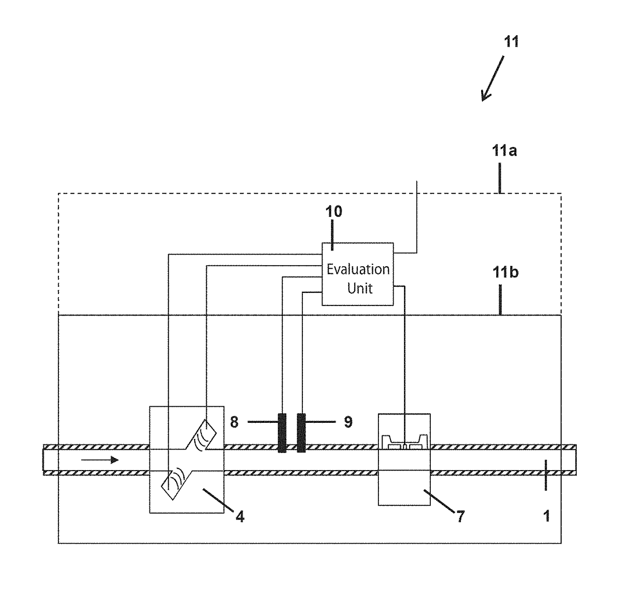
[0128]FIG. 5 shows the schematic configuration of a measuring apparatus 11 according to the present invention with a microthermal sensor 7 in a bypass gas line 6 to the main gas line 1. An element 5 which produces a pressure drop is provided in this case in the main gas line, so that a pressure drop is formed in operation via the bypass gas line, which leads to a gas flow 2 in the bypass gas line, wherein a characteristic flow splitting ratio 3 is obtained between the main gas line and the bypass gas line.

[0129]In the illustrated embodiment, the measuring apparatus comprises, in addition to the microthermal sensor 7, an evaluation unit 10 which is set up for carrying out a method according to the present invention, as well as an ultrasonic flow sensor 4, a pressure sensor 8 and a temperature sensor 9, which are typically arranged in the main gas line 1. Some of these components or all these components can be combined into a modular unit, wherein the evaluation unit 10 can be a compo...

third embodiment

[0136]FIG. 6 shows the schematic configuration of a measuring apparatus 11 according to the present invention in a bypass gas line 6 to the main gas line 1. An element 5 which produces a pressure drop is provided in this case in the main gas line, so that a pressure drop via the bypass gas line is formed in operation, leading to a gas flow 2 in the bypass gas line, wherein a characteristic flow splitting ratio 3 is formed between the main gas line and the bypass gas line.

[0137]In the illustrated embodiment, the measuring apparatus comprises an evaluation unit 10 which is set up to carry out a method according to the present invention, as well as an ultrasonic flow sensor 4 and a microthermal sensor 7 which are arranged in the bypass gas line 6. The measuring apparatus further comprises a pressure sensor 8 and a temperature sensor 9, which are mostly also arranged in the bypass gas line 1. Some of these components or all of these components can be combined into a modular unit, wherei...


PUM

PropertyMeasurementUnit
temperaturesaaaaaaaaaa
temperatureaaaaaaaaaa
pressureaaaaaaaaaa

Abstract

A method and a measuring apparatus for determining specific quantities for the gas quality in which the gas or gas mixture flows through an ultrasonic flow sensor as well as through a microthermal sensor, and the former is used for determining the sound and flow velocity and the latter for determining the thermal conductivity and the thermal capacity of the gas or gas mixture. The sound velocity, the thermal conductivity and the thermal capacity are subsequently used for the correlation of the specific quantities for the gas quality.

Description

RELATED APPLICATION[0001]This application claims priority to European Patent Application No. 14003855.5 filed Nov. 14, 2014, the entirety of which is incorporated by reference.BACKGROUND OF THE INVENTION[0002]The invention relates to a method and a measuring apparatus for determining specific quantities for the gas quality or energy consumption in domestic and industrial areas.[0003]The (natural) gas composition and thus the gas quality will fluctuate more frequently and strongly in future due to new sources of origin (biogas, liquefied gas from all regions of the world, hydrogen from the exploitation of excess current from the generation of alternative energy) and will thus have different effects on gas application processes, which may also include such that are negative. The processes could be adjusted to the fluctuating gas quality by direct measurement of specific quantities for the on-site gas quality in order to ensure optimal and secure operation. The specific quantities for ...

Claims


Application Information

Patent Timeline
Patent Type & Authority Patents(United States)
IPC IPC(8): G01F1/66G01N25/18G01N29/024G01N33/22G01N7/00G01N9/00G01N25/00
CPCG01F1/66G01N7/00G01N9/00G01N29/024G01N33/225G01N25/18G01N2291/02836G01N25/005
Inventor PRETRE, PHILIPPE
Owner MEMS
Why Eureka
Try Eureka