Swivel for mooring arrangement having an electric power generator which converts relative rotation between two elements into electric power

a technology of electric power generator and mooring arrangement, which is applied in the direction of mechanical vibration separation, special purpose vessels, vessel construction, etc., can solve the problems of large risk of cutting an external cable during deployment and retrieval, large risk of power and communication cables needing extensive, and high cost and impractical shielding, so as to reduce the number of discrete components in the system and reduce power loss. , the effect of cost saving

Active Publication Date: 2018-12-18
ABYSSUS MARINE SERVICES
View PDF7 Cites 6 Cited by
  • Summary
  • Abstract
  • Description
  • Claims
  • Application Information

AI Technical Summary

Benefits of technology

[0024]Preferably, the sensor array comprises several mooring lines extending in different directions from a moored structure and a swivel comprising a sensor. Here and in the claims, “a”, “an” or “the” should be construed as “(the) at least one”, e.g. “at least one swivel (each) comprising at least one sensor”. Including sensor(s) in the swivel reduces power loss and the number of discrete components in the system. Both of these factors contribute to a cost effective system.

Problems solved by technology

Fishing is restricted in a relatively large area due to the length of the mooring line.
However, there is a large risk for cutting an external cable during deployment and retrieval as described below.
Thus, power and communication cables would need extensive, expensive and impractical shielding.
This is time consuming and expensive.

Method used


Image

  • Swivel for mooring arrangement having an electric power generator which converts relative rotation between two elements into electric power
  • Swivel for mooring arrangement having an electric power generator which converts relative rotation between two elements into electric power
  • Swivel for mooring arrangement having an electric power generator which converts relative rotation between two elements into electric power

Examples


first embodiment

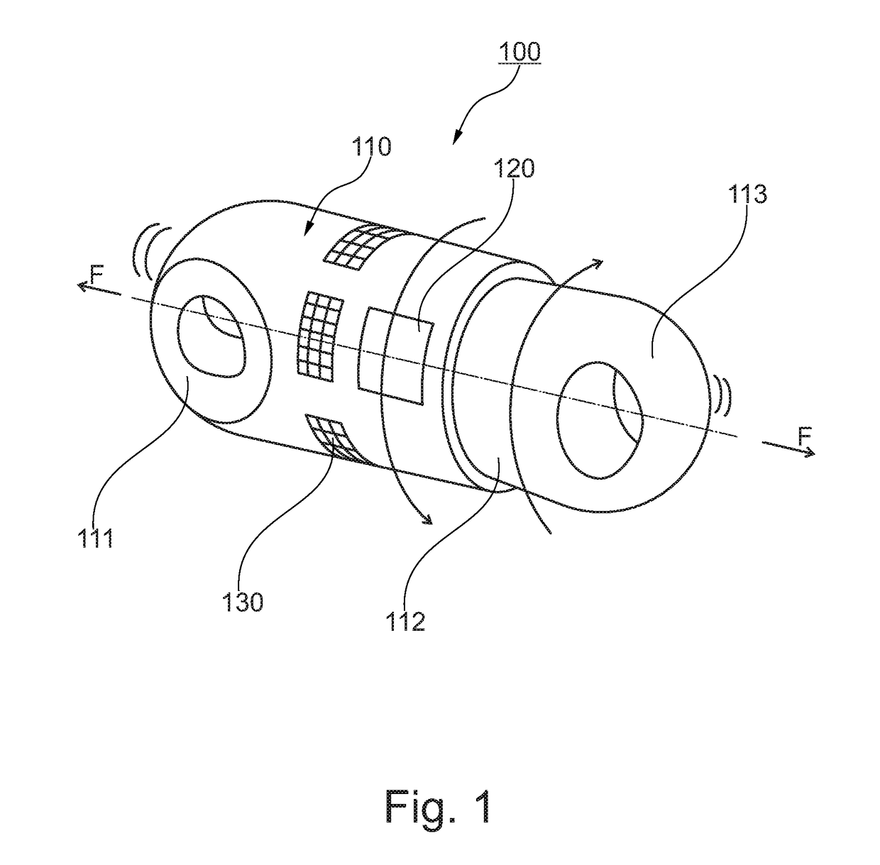
[0035]FIG. 1 illustrates a swivel 100 according to the invention. The swivel has a first element 110 with a first line coupler 111 and a second element 112 with a second line coupler 113. The line couplers 111, 113 are for connecting to segments of a mooring line, and are simply shown as eyes for connection to a chain or rope by means of shackles. The exact type of connection(s) to segments of a mooring line is of little or no concern here. The second element 112 may rotate relative to the first element 110 as required in any swivel for a mooring line. The swivel 100 of the invention also comprises an electric power generator 120 converting a relative rotation between the first element 110 and the second element 112 into electric power. In the embodiment shown on FIG. 1, sensors 130, such as acoustic transducers and transmitters, can also be included in the swivel according to the invention.

second embodiment

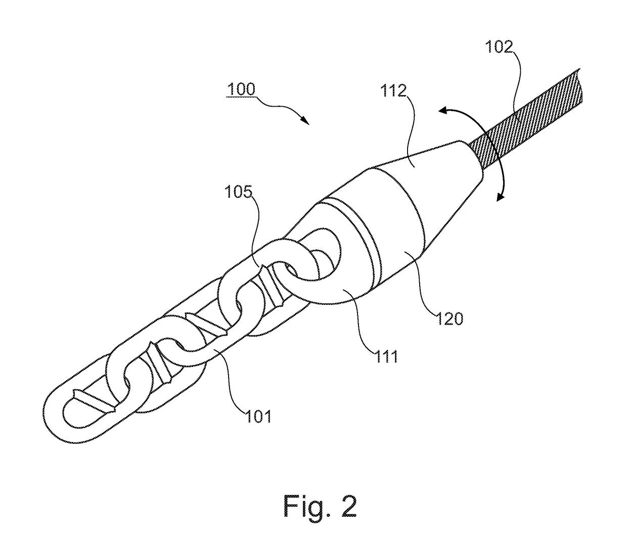
[0036]FIG. 2 illustrates the swivel 100. The first line coupler 111 is attached to a chain 101 (first segment) by means of a shackle 105. The second element 112 of the swivel is attached to a rope 102 (second segment). As noted in the introduction, the term “rope” means a rope of any material, e.g. a rope made of synthetic fibres and / or a steel wire. When a longitudinal pull is applied to the mooring line, the rope 102 tends to “unwind” and cause a first rotation of the second element 112 relative to the first element 110 and chain 101. Once the pull is relieved, the rope 102 tends to cause a rotation of the second element 112 relative to the first element 110 in a direction opposite to the first rotation. Preferably, both directions of relative rotation generate electric power in the generator 120.

[0037]The generator 120 as such is not part of the invention, and any suitable type may be used with the present invention. As well known, an electric generator generally comprises a wind...


PUM

PropertyMeasurementUnit
electric poweraaaaaaaaaa
tensionaaaaaaaaaa
torqueaaaaaaaaaa

Abstract

A swivel (100) for a mooring line comprises a first element (110) with a first line coupler (111) and a second element (112) with a second line coupler (113). The first element (110) and the second element (112) are rotatable relative to each other. An electric power generator (120) converts a relative rotation between the first element (110) and the second element (112) into electric power. In use, the line couplers (111, 113) are attached to separate segments of the mooring line. A pull F applied to or relieved from the mooring line causes the relative rotation. The swivel preferably contains a battery and a control unit, and may supply power to one or more sensors (130) built into or external to the swivel (100). A system for monitoring a mooring arrangement is also disclosed.

Description

BACKGROUNDField of the Invention[0001]The present invention concerns a swivel for a mooring line and a system for monitoring a mooring arrangement comprising at least one mooring line with the swivel.Prior and Related Art[0002]In several applications, a moored structure is kept substantially stationary at a predetermined spot at sea, e.g. at a sea surface, by one or more mooring lines, each extending in a particular direction, i.e. azimuth and inclination, from the structure to a fixed point such as an anchor embedded in the sea floor. The present invention relates to mooring in general. Examples from the oil and gas industry include floating platforms, drilling vessels and loading buoys. Other examples of moored structures include aquaculture plants, wind or wave generators at sea and generators converting tidal currents to electric power.[0003]In the following description and claims, a mooring line should be construed as an assembly of chains and / or ropes extending from the moored...

Claims


Application Information

Patent Timeline
Patent Type & Authority Patents(United States)
IPC IPC(8): B63B21/20H02K7/18F16G15/08B63B21/04B06B1/06G01L5/10B63B35/44B63B21/00
CPCB63B21/04B06B1/06B63B21/20F16G15/08H02K7/1807H02K7/1892G01L5/10B63B2021/008B63B35/4413B63B2021/003
Inventor KYRRE, TJOM J.
Owner ABYSSUS MARINE SERVICES
Why Eureka
Try Eureka