
Control valve with external relief bias member
a technology of bias member and control valve, which is applied in the direction of machine/engine, process and machine control, instruments, etc., can solve the problems of difficult configuration of actuator and valve to provide adequate valve movement and pressure relief in a compact configuration, and achieve the effect of increasing the volume of the material
- Summary
- Abstract
- Description
- Claims
- Application Information
AI Technical Summary
Benefits of technology
Problems solved by technology
Method used
Image

Examples
Embodiment Construction
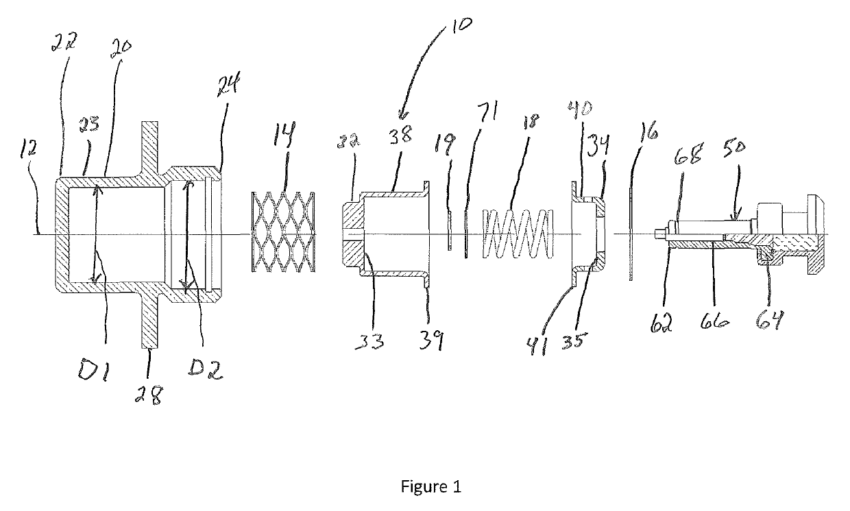
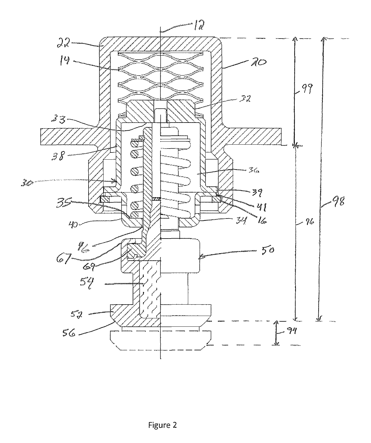
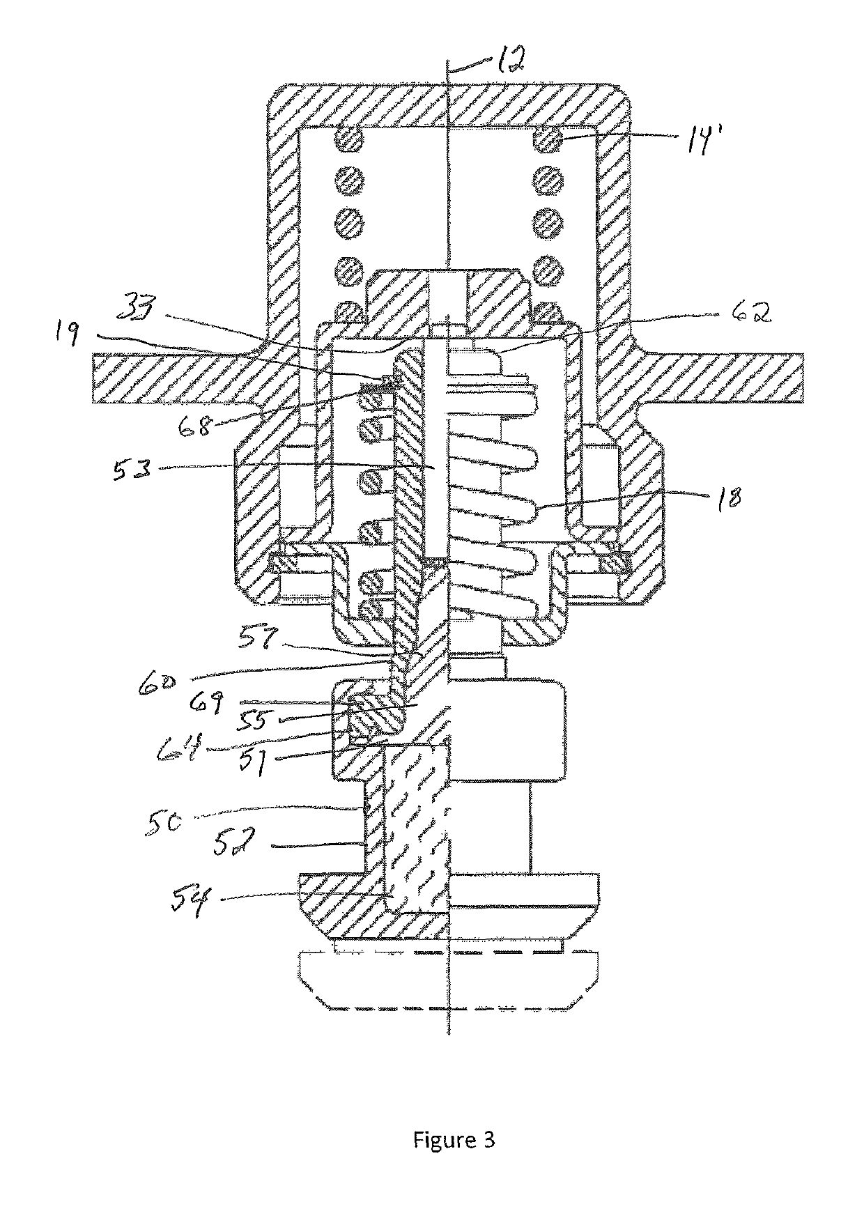
[0018]With reference to FIGS. 1-4B, wherein like numerals represent similar parts throughout the several figures, a first embodiment of a control valve with a relief bias member outside of a fluid housing is generally designated by the reference numeral 10 (hereafter “control valve 10”). The control valve 10 is configured to provide reliable and efficient control of fluids through a system as the temperature of the fluid in the system changes. The present disclosure primarily describes a control valve 10 for use in fluid systems requiring valve movement that is large relative to the distance between an outer wall and the valve seat of a chamber.
[0019]Referring to one embodiment of the control valve 10, depicted in FIGS. 1 and 2, a cap 20 forms a hollow cylindrical chamber, though other shapes may be used. The cap 20 has a closed end 22 transverse to a longitudinal axis 12 and a side wall 23 that extends axially away from the closed end 22 to an open end 24. The side wall 23 has a fi...
PUM
 Abstract
Description
Claims
Application Information