
Valve stem installation device

Inactive Publication Date: 2007-02-27
DURR SYST INC
View PDF40 Cites 0 Cited by
  • Summary
  • Abstract
  • Description
  • Claims
  • Application Information

AI Technical Summary

Benefits of technology

[0007]One of the advantages of the present invention is that processing time for inserting the valve stem in the valve stem aperture is reduced. Specifically, the relative movement between the valve stem and the valve stem aperture can be maximized prior to the locating step and the first and second sensor can be spaced from one another to accommodate the braking capacity of the system. In other words, the invention substantially eliminates time delays associated with confirming the location of the valve stem aperture that are common in prior art locating systems.

Problems solved by technology

Such manual processes are expensive because of the labor and time involved.
In addition, operations performed manually are subject to a relatively greater frequency of processing errors in comparison to robot-performed processes.

Method used


Image

  • Valve stem installation device
  • Valve stem installation device
  • Valve stem installation device

Examples


Embodiment Construction

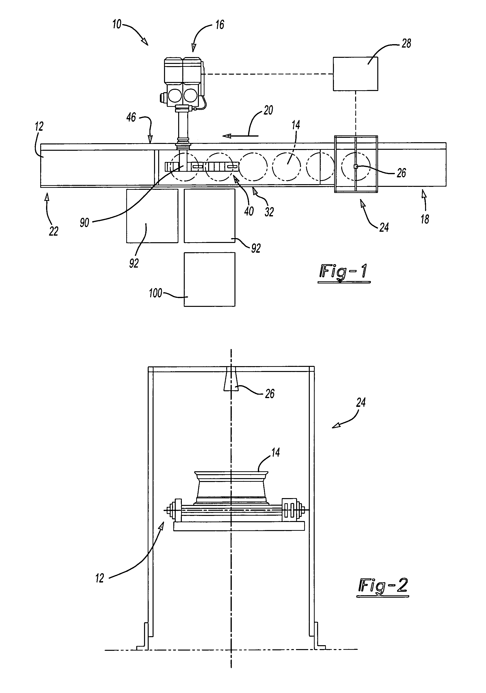
[0016]Referring now to FIG. 1, the present invention provides a method and apparatus 10 for inserting a valve stem in a valve stem aperture defined by a wheel. The apparatus 10 includes a conveyor 12 for moving wheels 14 past a robotic apparatus 16. Valve stems are inserted in the valve stem aperture defined by the wheel 14 by the robotic apparatus 16. Wheels 14 can be received at a beginning 18 of the conveyor 12 and move in a direction 20 to an end 22 of the conveyor 12.

[0017]Referring now to FIGS. 1 and 2, during movement of the wheel 14 between the beginning 18 and end 22 of the conveyor 12, the wheel 14 passes through an identification station 24. The identification station 24 can include a camera 26 for identifying the wheel 14 from a plurality of differently configured wheels. When a wheel 14 moves within the visual range of the camera 26, the camera 26 communicates an image of the wheel 14 to a controller 28. The image includes structural features of the wheel 14 including t...


PUM

PropertyMeasurementUnit
Angular velocityaaaaaaaaaa

Abstract

A valve stem installation system includes a robotic arm for moving a valve stem insertion device around the lip of wheel. The system also includes a pair of valve stem aperture sensors positioned on the robotic arm adjacent the valve stem insertion device and moveable around the lip of the wheel. The sensors can be positioned on opposite sides of the valve stem insertion device. When the first sensor locates the valve stem aperture, movement of the robotic arm can be slowed. When the second sensor locates the valve stem aperture, movement of the robotic arm can be stopped. The conveyor unit can include an identification station to sense the configuration of the wheel. A controller can select the appropriate valve stem to insert in the valve stem aperture in response to the sensed configuration of the wheel.

Description

RELATED APPLICATIONS[0001]This application claims the benefit of the provisional patent application 60 / 453,262 for a VALVE STEM INSTALLATION SYSTEM AND METHOD OF INSTALLING VALVE STEM, filed on Mar. 10, 2003, and claims the benefit of the provisional patent application 60 / 460,153 for a TIRE PRESSURE MONITORING VALVE STEM INSTALLATION SYSTEM AND METHOD OF INSTALLING TIRE PRESSURE MONITORING VALVE STEM, filed Apr. 3, 2003, which are hereby incorporated by reference in their entireties.FIELD OF THE INVENTION[0002]The subject invention relates to the assembly of wheels, and more particularly to an apparatus and method for locating a valve stem aperture in a wheel and mounting the valve stem to the wheel.BACKGROUND OF THE INVENTION[0003]In the past, a valve stem was manually mounted to a wheel with a stem-inserting tool. Such manual processes are expensive because of the labor and time involved. In addition, operations performed manually are subject to a relatively greater frequency of p...

Claims


Application Information

Patent Timeline
IPC IPC(8): B23P21/00B23P19/10B23P19/04B60C25/18
CPCB23P19/04B60C25/18Y10T29/49769Y10T29/53591Y10T29/49526Y10T29/53061Y10T29/4941Y10T29/53087Y10T29/4978Y10T29/49778
Inventor PELLERIN, DANSINKE, CHAD A.HOY, BRIAN
Owner DURR SYST INC
Learn More