
Sunshade Assembly Having a Buffer Unit

Inactive Publication Date: 2012-07-19
MACAUTO IND CO LTD
View PDF0 Cites 4 Cited by
  • Summary
  • Abstract
  • Description
  • Claims
  • Application Information

AI Technical Summary

Benefits of technology

[0006]Therefore, the object of the present invention is to provide a sunshade assembly that has a buffer unit which can prevent production of noise and vibration when a sunshade cloth is moved from a stretched position to a wound position.

Problems solved by technology

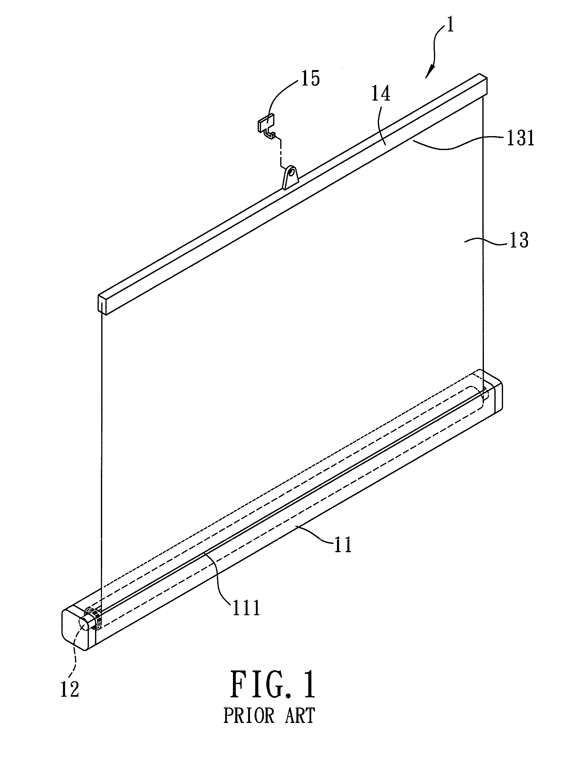
The impact may generate noise and cause vibration in the components of the conventional sunshade assembly.
Hence, the conventional sunshade curtain 1 lacks sophistication, and is not suitable for use in luxury cars.

Method used


Image

  • Sunshade Assembly Having a Buffer Unit
  • Sunshade Assembly Having a Buffer Unit
  • Sunshade Assembly Having a Buffer Unit

Examples


Embodiment Construction

[0015]Before the present invention is described in greater detail, it should be noted that like elements are denoted by the same reference numerals throughout the disclosure.

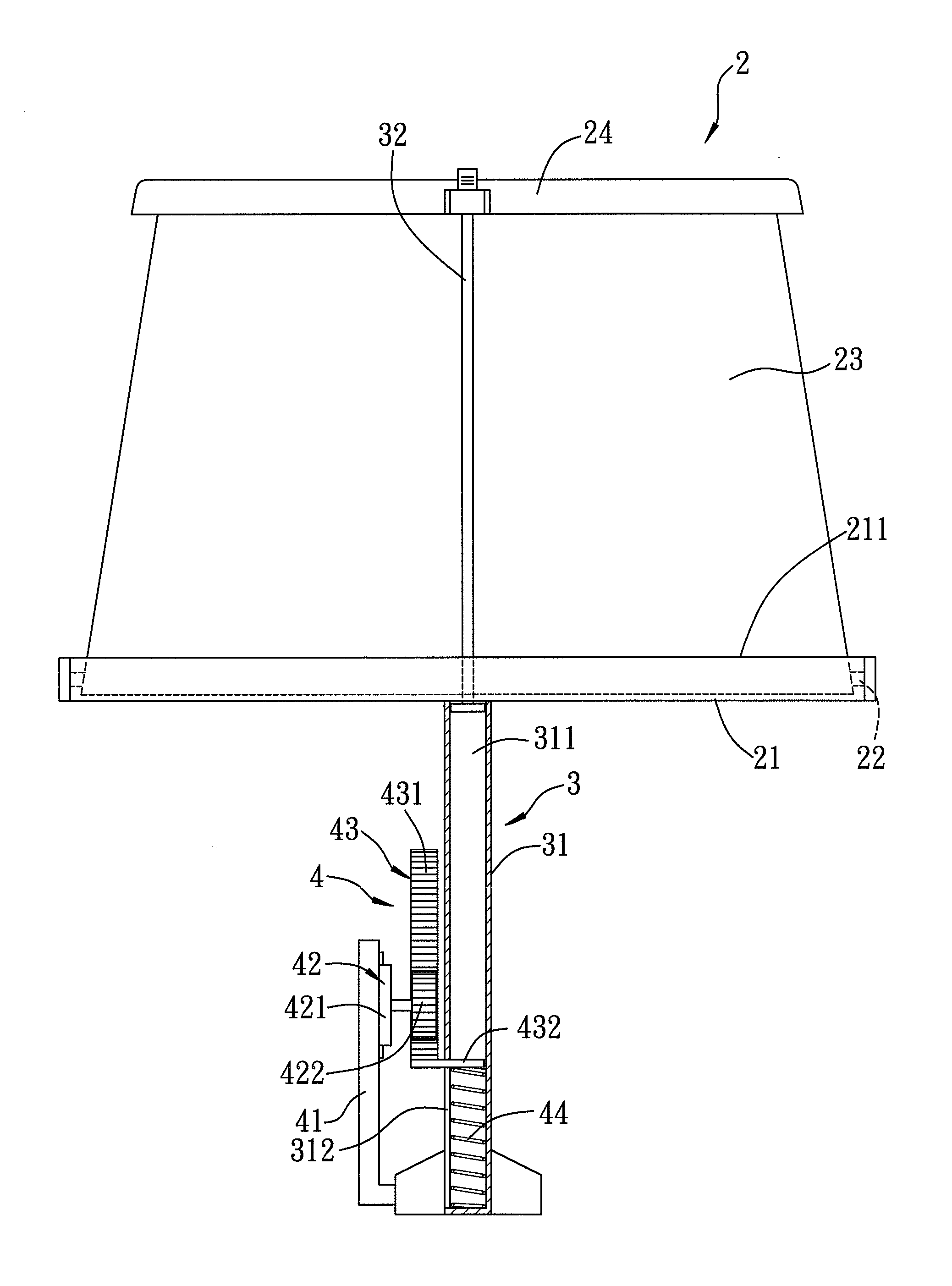
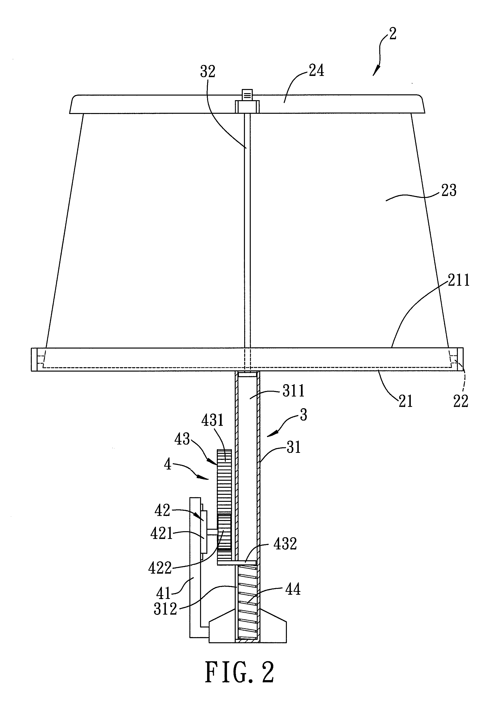
[0016]Referring to FIGS. 2 and 3, a sunshade assembly according to the first preferred embodiment of the present invention is shown to comprise a sunshade unit 2, a guide unit 3, and a buffer unit 4. The sunshade assembly of the present invention is adapted to be installed on a door (not shown) of a vehicle to cover a corresponding side window (not shown).

[0017]The sunshade unit 2 includes a housing 21 having a top opening 211, a rewindable winding shaft 22 mounted rotatably in the housing 21, a sunshade cloth 23 unwindably wound around the winding shaft 22, and a pull rod 24 connected to one end of the sunshade cloth 23 that is distal from the winding shaft 22 and disposed external to the top opening 211. The sunshade unit 2 may further include at least one biasing element (not shown) having one end that is fix...


PUM


Abstract

A sunshade assembly includes a housing having a top opening, a winding shaft mounted rotatably in the housing, a sunshade cloth wound around the winding shaft, a pull rod connected to the sunshade cloth and disposed external to the top opening, a tubular casing mounted below the housing, a guide rod extending downward from the pull rod and slidable in the tubular casing, a buffer disposed beside the tubular casing to provide a buffer resistance to the guide rod, and a driven member driven by the guide rod and moving the buffer. When the sunshade cloth is moved by the winding shaft to a wound position from a stretched position external to the housing, the guide rod is moved downward along with the pull rod until the guide rod pushes downward the driven member, thereby reducing a downward moving speed of the guide rod.

Description

BACKGROUND OF THE INVENTION[0001]1. Field of the Invention[0002]The invention relates to a sunshade, and more particularly to a sunshade assembly that is adapted to be installed on a side window of a vehicle and that has a sunshade cloth which can be wound automatically.[0003]2. Description of the Related Art[0004]Referring to FIG. 1, a conventional sunshade assembly 1 includes a housing 11 having a top opening 111, a winding shaft 12 mounted rotatably in the housing 11, a sunshade cloth 13 wound around the winding shaft 12, a pull rod 14 connected to one end 131 of the sunshade cloth 13 that is distal from the winding shaft 12, and a hanging seat 15 for hanging of the pull rod 14 when the sunshade cloth 13 is unwound from the winding shaft 12.[0005]To use the conventional sunshade assembly 1, the user pulls out the sunshade cloth 13 from the housing 11 via the top opening 111, and the pull rod 14 is hung on the hanging seat 15, thereby placing the sunshade cloth 13 in a stretched p...

Claims


Application Information

Patent Timeline
IPC IPC(8): E06B9/44
CPCE06B9/42E06B9/60B60J1/2036E06B9/68B60J1/2022E06B9/66
Inventor LIN, PAUL
Owner MACAUTO IND CO LTD
Learn More