Partitioning method for a work space of a robot

Active Publication Date: 2020-04-02
TECHMAN ROBOT INC
View PDF9 Cites 0 Cited by
  • Summary
  • Abstract
  • Description
  • Claims
  • Application Information

AI Technical Summary

Benefits of technology

The present patent application provides a partitioning method for the working space of a robot that can simplify the process of setting partitioning planes and improve the efficiency of the robot operation. The method allows for the formation of designated sections, extended sections, and a full partitioning plane that combines these sections. This full partitioning plane can be used to create two working regions for the robot, with different levels of access. The method also includes restricting the robot from entering certain areas and operating it at different speeds based on its location. Overall, this method provides a more efficient and simplified way of partitioning a robot's working space.

Problems solved by technology

When the robot has to collaborate with staff, it is an important issue to ensure safety of the staff during the collaboration.
However, the optical sensors or the machine vision devices require not only installation space but also specific auxiliary software, which increases installation cost and lowers competitiveness of the product.
Although the robot platform can be marked with the different colors to indicate the different exposure levels to danger corresponding to the different working regions, it cannot take into account that an actual working space of the robot is a three-dimensional space where boundary planes for the working regions in the working space cannot be substantially marked by colors.
However, not only marking the boundary planes by coordinate is tedious, but also the boundary planes marked by coordinates are not easy to be visualized for correspondence to the substantial configuration of the working regions.
That is, the conventional methods are prone to mistakenly position the robot in or across the human-machine collaboration region so that the robot cannot move at a full speed due to a speed limitation imposed around the human-machine collaboration region, which lowers efficiency of the robot.

Method used


Image

  • Partitioning method for a work space of a robot
  • Partitioning method for a work space of a robot
  • Partitioning method for a work space of a robot

Examples


Embodiment Construction

[0020]In the following detailed description of the preferred embodiments, reference is made to the accompanying drawings which form a part hereof, and in which is shown by way of illustration specific embodiments in which the invention may be practiced. In this regard, directional terminology, such as “top,”“bottom,”“front,”“back,” etc., is used with reference to the orientation of the Figure (s) being described. The components of the present invention can be positioned in a number of different orientations. As such, the directional terminology is used for purposes of illustration and is in no way limiting. Accordingly, the drawings and descriptions will be regarded as illustrative in nature and not as restrictive.

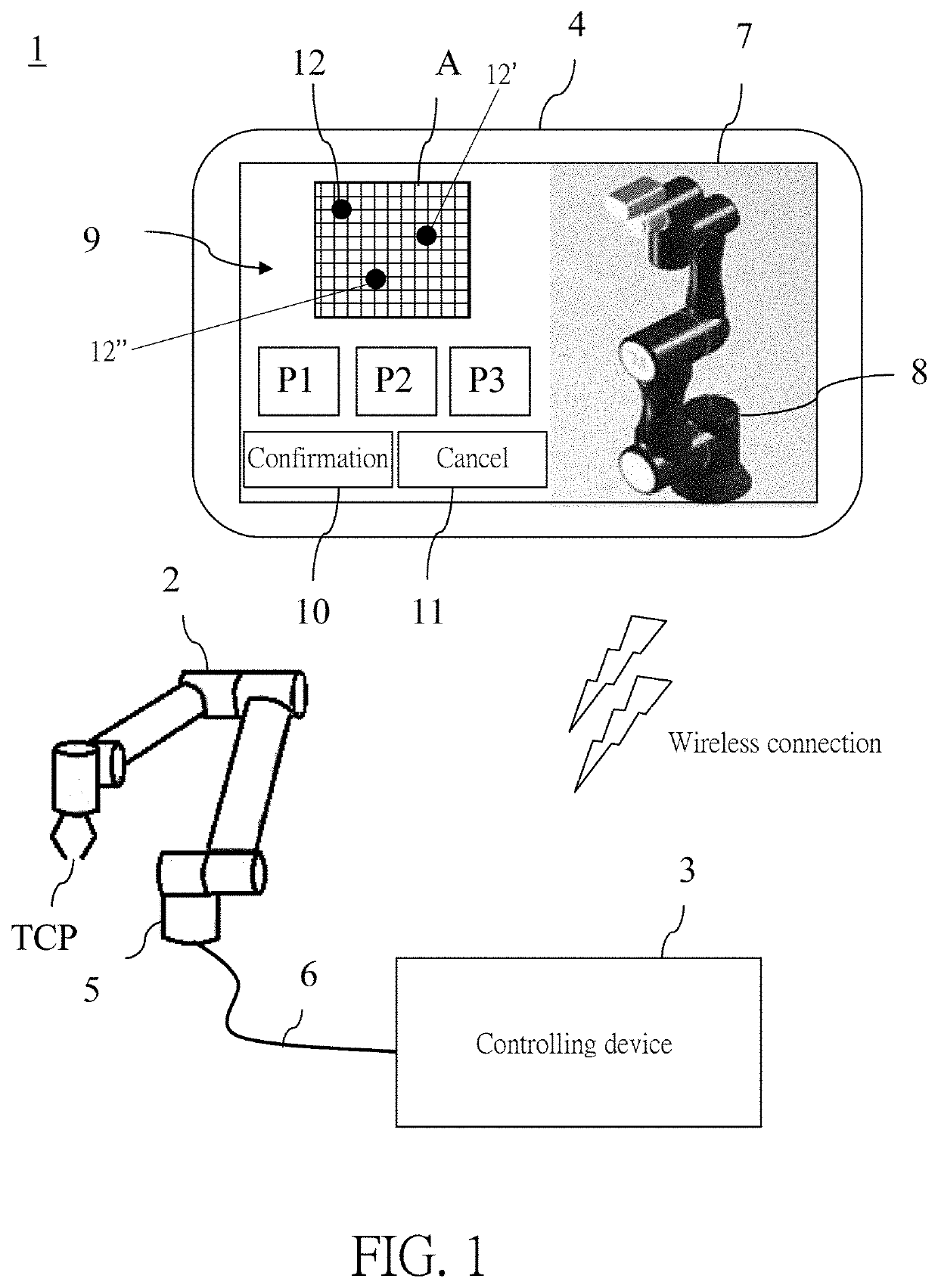
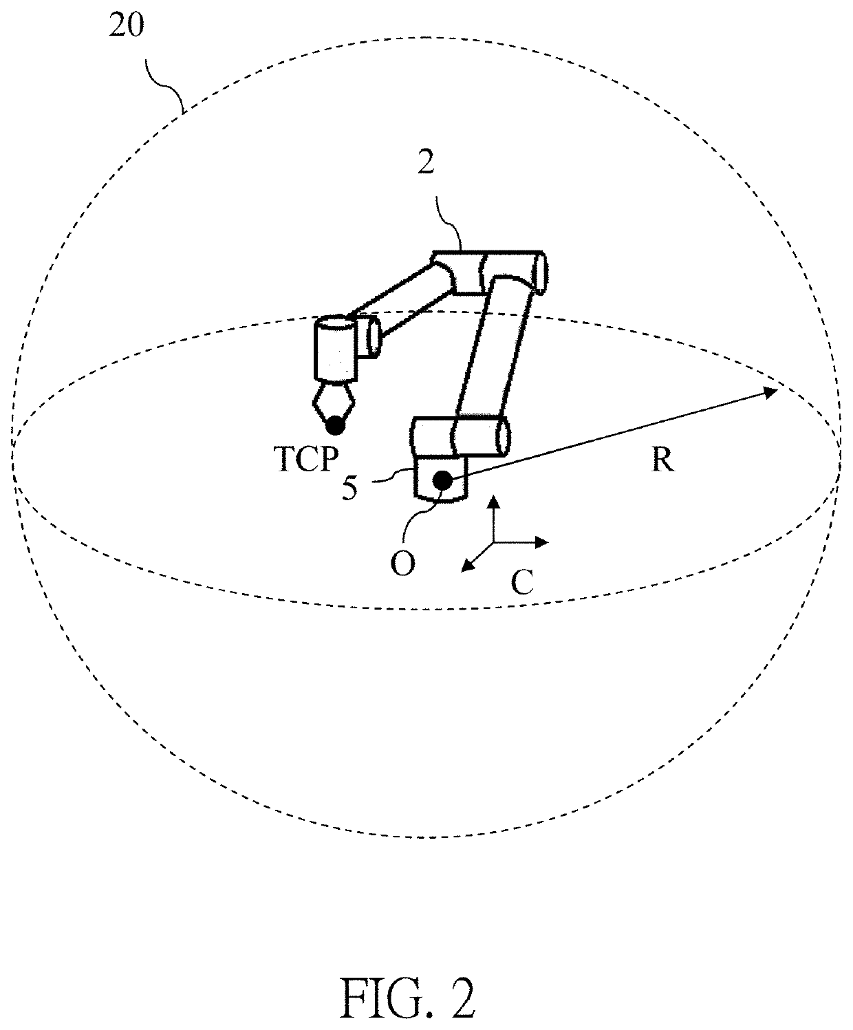
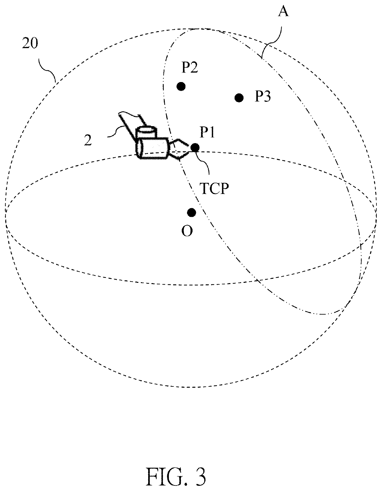
[0021]Please refer to FIG. 1, FIG. 2, and FIG. 3. FIG. 1 is a diagram of a control system 1 for controlling a robot 2 according to an embodiment of the present application. FIG. 2 is a diagram of a working space 20 of the robot 2 according to the embodiment of the present ...


PUM


Abstract

The partitioning method for a working space of a robot includes defining the working space of the robot; setting a plurality of partitioning planes based on at least three non-collinear points in the working space; if the setting of the plurality of partitioning planes is completed, defining partitioning lines by intersecting the plurality of partitioning planes; dividing the plurality of partitioning planes into a plurality of designated sections and a plurality of extended sections based on the partitioning lines; combining the plurality of designated sections for constructing a full partitioning plane; partitioning the working space into two working regions based on the full partitioning plane; and setting the working region containing an origin of the robot as an operation region. Therefore, the partitioning process can be simplified.

Description

BACKGROUND OF THE INVENTION1. Field of the Invention[0001]The invention relates to a robot, and more particularly, to a robot with human-machine collaboration function and a method for planning working regions allowing different moving speeds of the robot according to an operator's risk levels in the working regions respectively.2. Description of the Prior Art[0002]A robot is agile in moving, precise in positioning, and robust in operation, which brings an advantage in production and assembly on production lines. When the robot has to collaborate with staff, it is an important issue to ensure safety of the staff during the collaboration.[0003]As disclosed by US patent US20160167231, to ensure safety of the staff working in working regions of the robot, optical sensors or machine vision devices are often utilized to set safety boundaries for planning the working regions. Once an operator is detected to cross the safety boundaries and exposed in an operation region of the robot, a mov...

Claims


Application Information

Patent Timeline
IPC IPC(8): B25J9/16G05B19/401
CPCG05B19/401B25J9/1692B25J9/1653B25J9/1697B25J9/1676G05B2219/39082
Inventor WANG, PEI-JUIHSIEH, CHI-MOTSAI, YUN-HSUANSHIA, SHAO-JIHUANG, SHIH-JUNG
Owner TECHMAN ROBOT INC
Why Eureka
Try Eureka