Motor driven compressor

a motor-driven compressor and compressor technology, which is applied in the direction of liquid fuel engines, machines/engines, rotary piston liquid engines, etc., can solve the problems of difficulty in restarting the rotation control of the rotor, and affecting the smooth restart of the conventional motor-driven compressor

Active Publication Date: 2019-10-08
TOYOTA IND CORP
View PDF10 Cites 2 Cited by
  • Summary
  • Abstract
  • Description
  • Claims
  • Application Information

AI Technical Summary

Benefits of technology

[0005]It is an object of the present invention to provide a motor-driven compressor that may be smoothly restarted.

Problems solved by technology

When the reverse rotation speed of the rotor exceeds a predetermined speed, it is difficult to restart the rotation control of the rotor.
Therefore, when restarting operation of the motor-driven compressor, immediate restarting of the rotor rotation control may be hindered.
In this manner, the conventional motor-driven compressor cannot be smoothly restarted.

Method used


Image

  • Motor driven compressor
  • Motor driven compressor
  • Motor driven compressor

Examples


Embodiment Construction

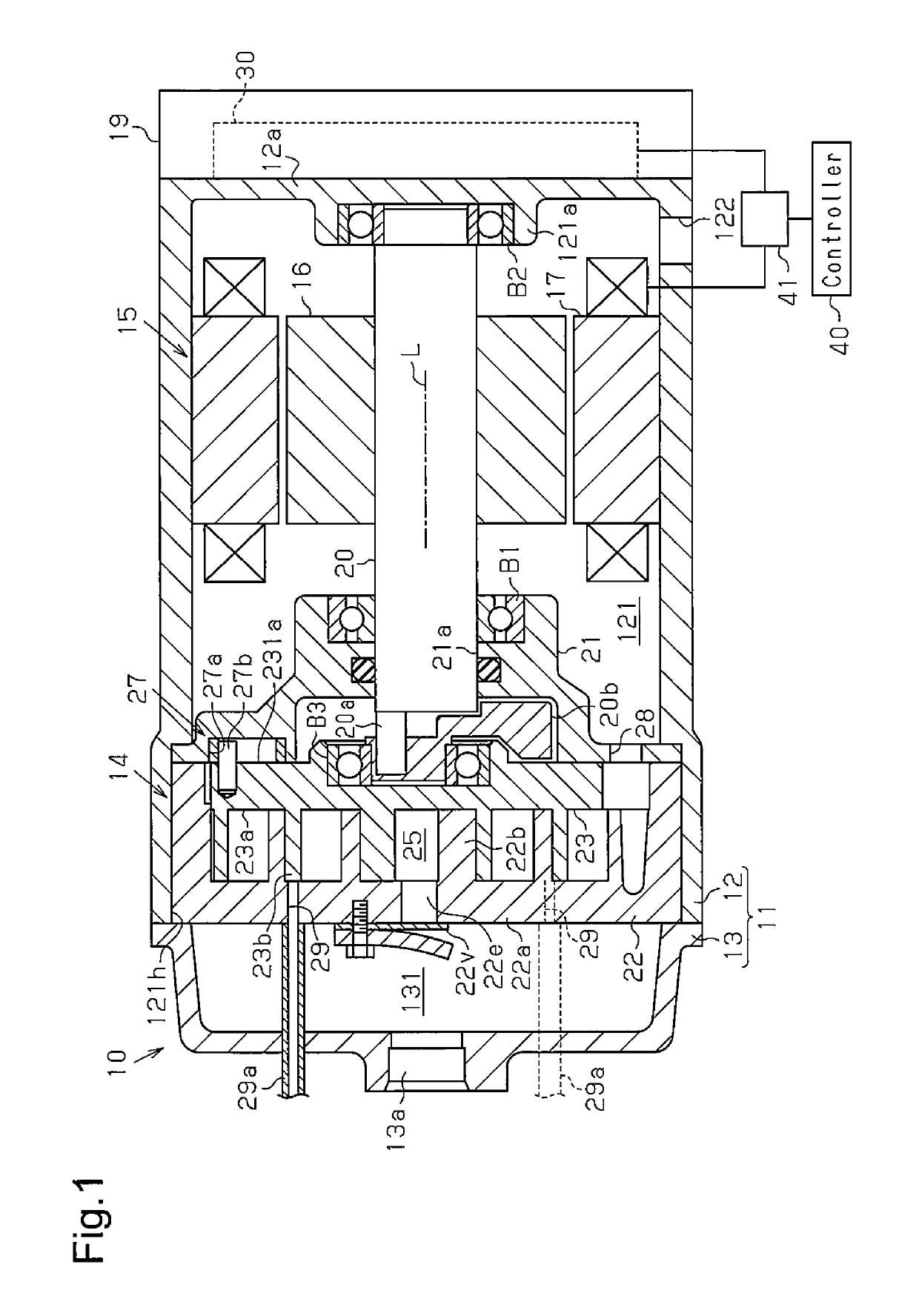
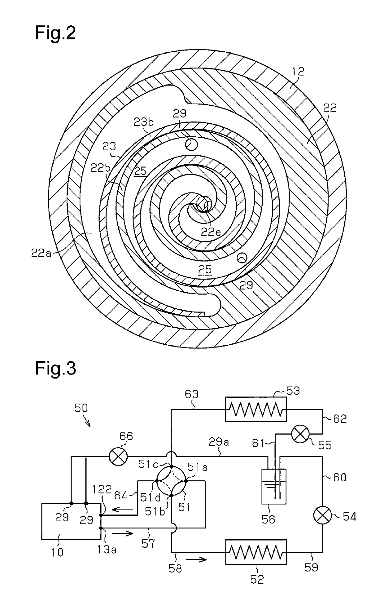
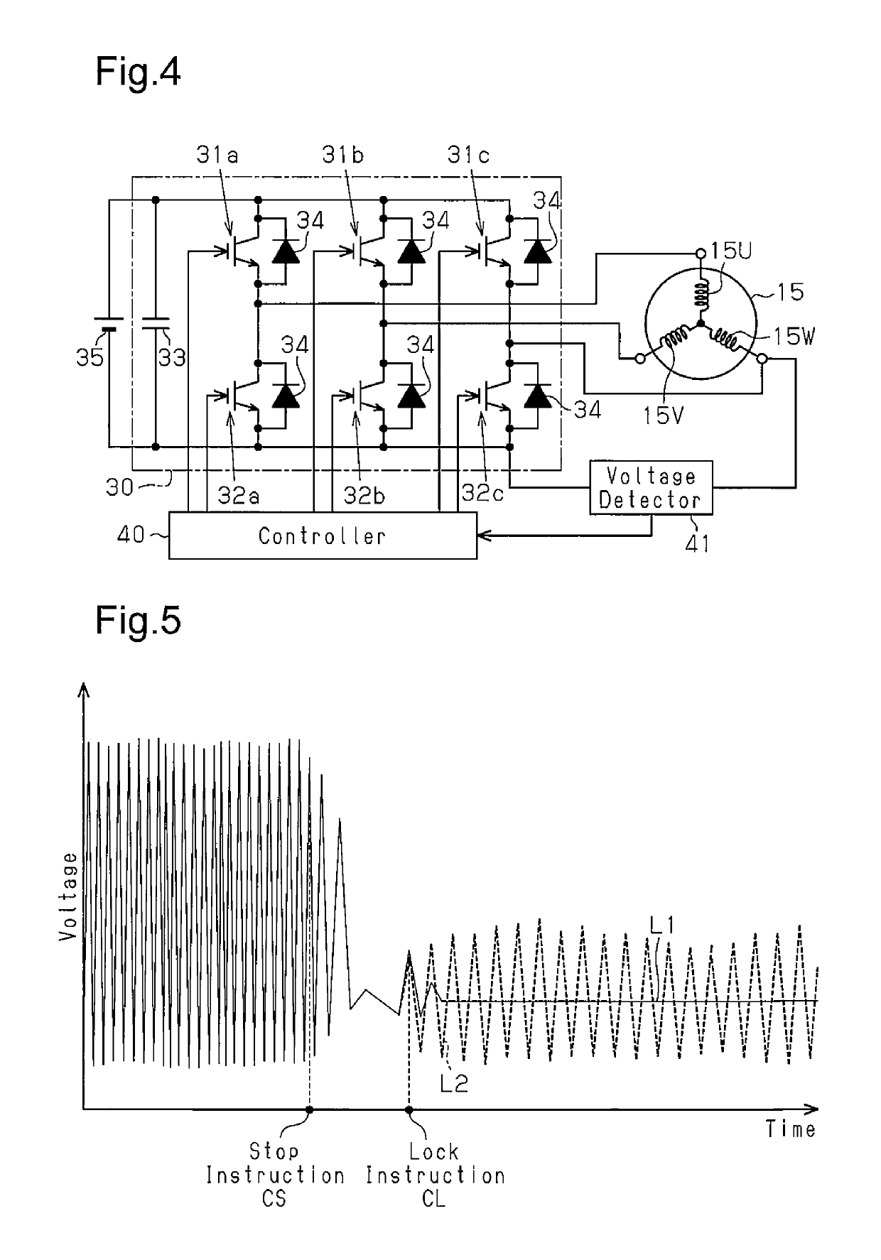
[0014]One embodiment of a motor-driven compressor will now be described with reference to FIGS. 1 to 5. The motor-driven compressor of the present embodiment may be installed in a vehicle for use with a vehicle air-conditioner.

[0015]As shown in FIG. 1, a motor-driven compressor 10 includes a housing 11 formed from a metal material (e.g., aluminum). The housing 11 may include a motor housing 12 and a discharge housing 13. The motor housing 12 includes an open end (left end in FIG. 1) forming an opening 121h. The discharge housing 13 is coupled to the open end. The motor housing 12 and the discharge housing 13 may each be cylindrical. The motor housing 12 accommodates a compression unit 14 that compresses a refrigerant and an electric motor 15 that drives the compression unit 14.

[0016]The motor housing 12 includes an end wall 12a at the opposite side of the opening 121h. A cylindrical shaft support portion 121a projects from a central portion of the end wall 12a toward the opening 121...


PUM


Abstract

A motor-driven compressor includes a compression unit that includes movable and fixed scrolls and a compression chamber, an electric motor that includes a rotor and drives the compression unit, a motor drive circuit that drives the electric motor, an injection port that draws intermediate pressure refrigerant into the compression chamber, a controller that performs rotation control on the rotor, and a voltage detector that detects a terminal voltage of the electric motor. The compression unit compresses low pressure refrigerant drawn into the compression chamber to discharge high pressure refrigerant. The controller is configured to output a stop instruction to deactivate the rotation control of the rotor, determine a rotation condition of the rotor based on the voltage detected by the voltage detector after outputting the stop instruction, and perform, based on the determination, restart preparation control that includes outputting a lock instruction to electrically stop rotation of the rotor.

Description

CROSS-REFERENCE TO RELATED APPLICATIONS[0001]This application is based upon and claims the benefit of priority from prior Japanese Patent Application No. 2013-238097, filed on Nov. 18, 2013, the entire contents of which are incorporated herein by reference.BACKGROUND OF THE INVENTION[0002]The present invention relates to a motor-driven compressor including an injection port that draws intermediate pressure refrigerant into a compression chamber formed by the engagement of a fixed scroll and a movable scroll.[0003]Japanese Laid-Open Patent Publication No. 2003-120555 describes a motor-driven scroll compressor in which an injection pipe is connected to an injection port of a compression chamber. A vapor-liquid separator is connected to the injection pipe. The injection pipe includes a check valve. In a refrigeration cycle, the check valve opens the injection pipe during a high load operation (e.g., heating operation) and closes the injection pipe during a low load operation (e.g., coo...

Claims


Application Information

Patent Timeline
Patent Type & Authority Patents(United States)
IPC IPC(8): F04C14/06F04C2/02F04C18/02F04C28/06H02P27/08
CPCF04C28/06F04C14/06F04C2/025F04C18/0215F04C2270/72H02P27/08
Inventor NAGATA, YOSHIKI
Owner TOYOTA IND CORP
Why Eureka
Try Eureka