Emergency stop cutting mechanism for a web rewinding device

a technology of rewinding device and stop cutting mechanism, which is applied in the direction of thin material handling, metal working apparatus, transportation and packaging, etc., can solve the problems of web impact damage, and achieve the effect of increasing handling safety

Active Publication Date: 2019-11-05
TECNAU INC
View PDF7 Cites 2 Cited by
  • Summary
  • Abstract
  • Description
  • Claims
  • Application Information

AI Technical Summary

Problems solved by technology

Since it can be challenging or impossible to fully stop a large roll of web in time, the cutting mechanism, instead, effectively decouples the roll's energy from the web before the available festoon storage has been taken up, and taut web impact damage occurs.

Method used


Image

  • Emergency stop cutting mechanism for a web rewinding device
  • Emergency stop cutting mechanism for a web rewinding device
  • Emergency stop cutting mechanism for a web rewinding device

Examples


Embodiment Construction

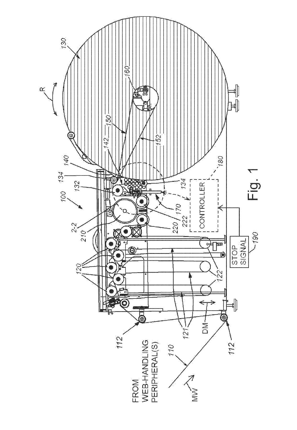
[0023]FIG. 1 is an exposed side view of a web winder 100 by way of non-limiting example. The winder 100 is arranged to rewind web 110 that has been processed by an upstream handling / utilization device, such as an electronic printer (not shown). The web moves downstream (motion arrow MW) through the winder 100 from an assembly of idler rollers 112, or other appropriate input arrangement, into a series of rollers 120 within the winder housing that suspend the web into a set of festooned loops 121. The loops 121 are weighted down by corresponding dancer bars or rollers 122 that move upwardly and downwardly (double arrow DM) in to build and take up an accumulated length of web. This accumulated length of web is used to compensate for changes in the rate between web fed into the winder 100 and web taken up by the winder roll 130. The web exits the festoon and passes through a serpentine path to at least one of the input roller(s) 132 and 134 that reside upstream of the roll 130. In an ex...


PUM


Abstract

This invention provides web-cutting mechanism that can be mounted in line at an appropriate location between the web-handling peripheral (printer) and a web roll. The cutting mechanism operates before the available storage in the winder festoon has been exhausted, and decouples the roll's energy from the web. The cutting mechanism can employ a blade that is drawn through the web solely by the movement of the web itself. The blade is mounted at a (e.g.) 45-degree angle to web travel, causing it to be pulled through the web. A negator spring assembly and associated cable drives the blade into the side edge of the web when a slide-mounted blade shuttle assembly is released by a latching pawl of a solenoid assembly. The solenoid is triggered by a signal indicating an emergency stop condition, such as an upstream jam.

Description

FIELD OF THE INVENTION[0001]This invention relates to web handling and feeding devices used in a flexible printing environment, and more particularly to web cutting devices.BACKGROUND OF THE INVENTION[0002]The use of rolled web (e.g. paper) in conjunction with a digital printer and various peripherals (e.g. cuttings, slitters, folders, stackers, etc.) has become a ubiquitous technique for producing a variety of printed materials. A typical web-handling / printing arrangement involves the use of a web unwinder, which can be driven at its core and / or its outer perimeter, and which passes through the various web-handling peripherals. The output web from the peripheral(s) can then be rewound, by a core-driven, or surface-driven rewinder onto an output web roll. This web roll can be used in further handling processes (e.g. further printing, cutting, stacking, folding, etc.). Typically one or more (e.g. dancer) loops are present between the components of the system, typically to sense the d...

Claims


Application Information

Patent Timeline
Patent Type & Authority Patents(United States)
IPC IPC(8): B26D5/00B65H26/00B65H26/02B26D5/08B26D7/26
CPCB65H26/02B65H26/00B26D7/2614B26D5/086
Inventor SILVA, STEPHEN E.MERCURIO, GREGORY
Owner TECNAU INC
Why Eureka
Try Eureka