

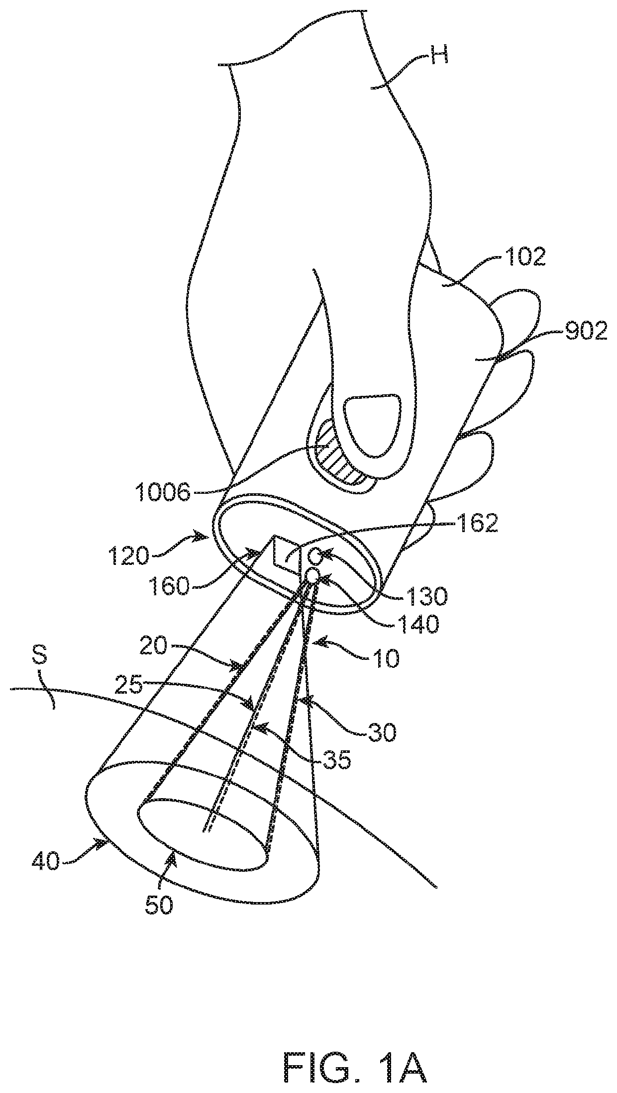
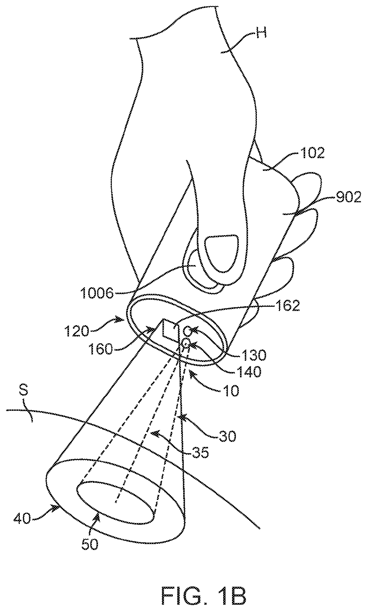
Spectrometry system with visible aiming beam
a spectrometry system and beam technology, applied in the field of spectrometry systems with visible aiming beams, can solve the problems of sensitivity and accuracy less than ideal, affecting the accuracy of measurement, so as to reduce the cost of prior spectrometers and improve the accuracy of measuremen
- Summary
- Abstract
- Description
- Claims
- Application Information
AI Technical Summary
Benefits of technology
Problems solved by technology
Method used
Image

Examples
Embodiment Construction
[0072]In the following description, various aspects of the invention will be described. For the purposes of explanation, specific details are set forth in order to provide a thorough understanding of the invention. It will be apparent to one skilled in the art that there are other embodiments of the invention that differ in details without affecting the essential nature thereof. Therefore the invention is not limited by that which is illustrated in the figure and described in the specification, but only as indicated in the accompanying claims, with the proper scope determined only by the broadest interpretation of said claims.
[0073]A better understanding of the features and advantages of the present disclosure will be obtained by reference to the following detailed description that sets forth illustrative embodiments, in which the principles of embodiments of the present disclosure are utilized, and the accompanying drawings.
[0074]The configurations disclosed herein can be combined ...
PUM
| Property | Measurement | Unit |
|---|---|---|
| irradiance | aaaaa | aaaaa |
| wavelengths | aaaaa | aaaaa |
| dimensions | aaaaa | aaaaa |
Abstract
Description
Claims
Application Information