Elbow prosthesis and method of use

a technology for elbows and prostheses, applied in the field of orthopaedics, can solve the problems of weaker soft tissue and significant bone erosion in patients, difficult use of unconstrained elbows, and insufficient strength of tissues

Active Publication Date: 2022-01-18
ACUMED
View PDF5 Cites 43 Cited by
  • Summary
  • Abstract
  • Description
  • Claims
  • Application Information

AI Technical Summary

Benefits of technology

[0015]The present invention provides in a further aspect, a semi-constrained total elbow prosthesis that includes an ulnar component having a bearing end and a stem with the stem being coupled to the bearing end and extending in a distal direction from the bearing, end. The prosthesis also has a humeral component that has a housing member and a proximally extending fixed stem. The semi-constrained elbow prosthesis may also have at least one bearing member that is coupled to an inside surface of the housing member. The bearing end is configured to be inserted into the housing member and articulate against the at least one bearing member to allow for motion between the ulnar component and humeral component.

Problems solved by technology

The inflammatory disease results in the patient having weaker soft tissue and significant bone erosion.
The weaker soft tissue and bone erosion makes the use of an unconstrained elbow more difficult in that the soft tissues are not of sufficient strength to properly contain the prosthetic components in contact with each other.
More specifically, currently no elbow implant designs exist that are specifically indicated for use to treat complex fractures of the distal humerus and / or proximal ulna.

Method used


Image

  • Elbow prosthesis and method of use
  • Elbow prosthesis and method of use
  • Elbow prosthesis and method of use

Examples


first embodiment

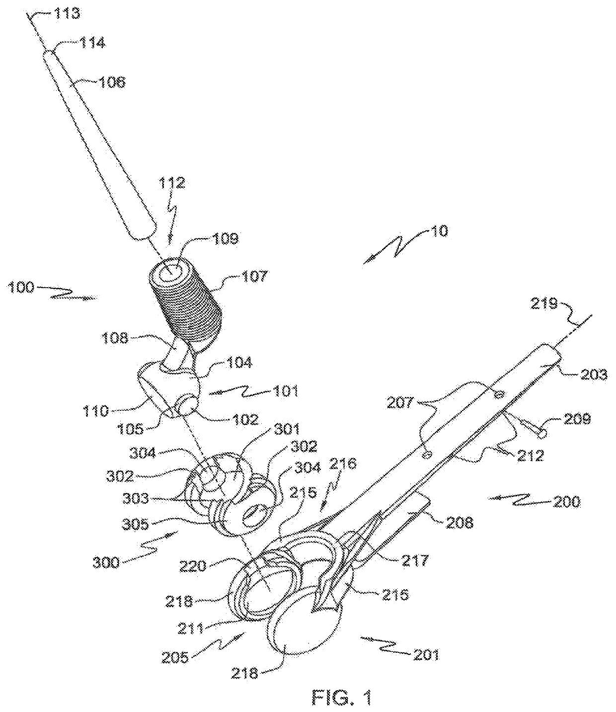
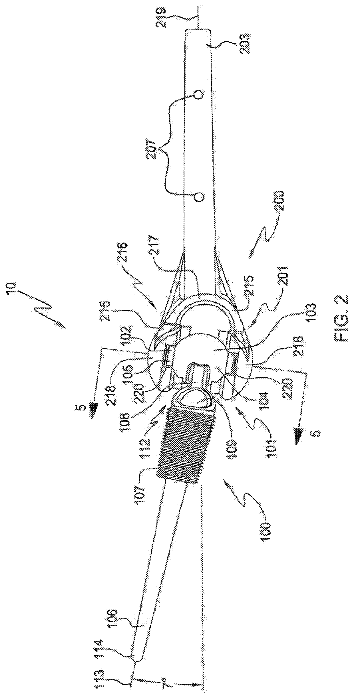
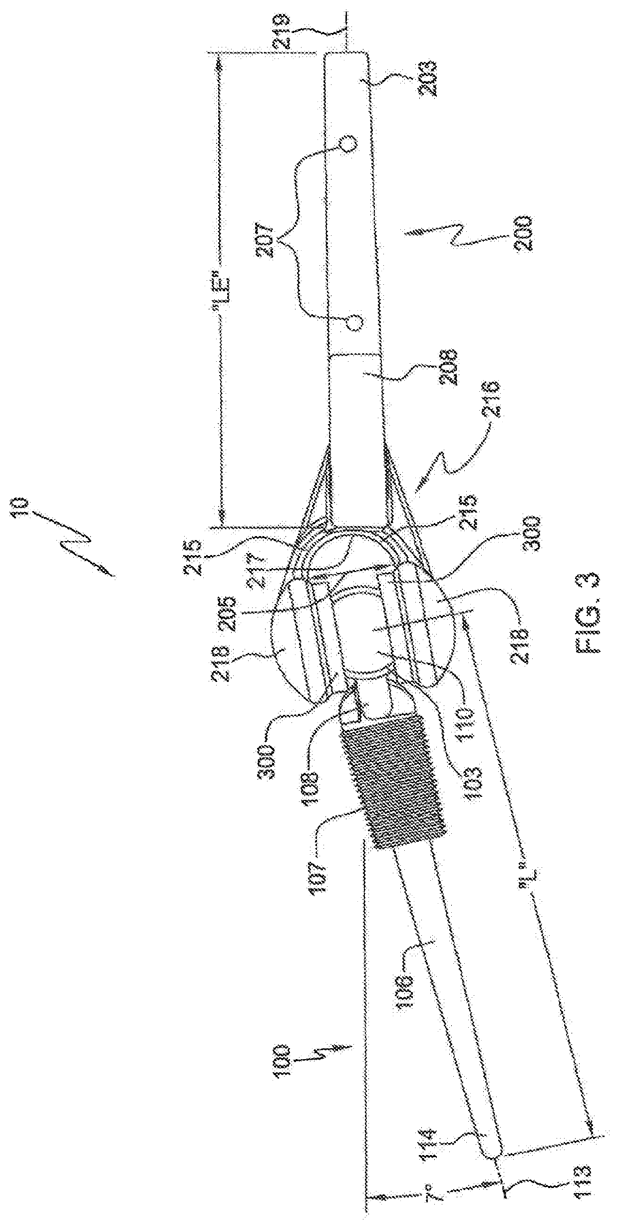
[0047]FIG. 1 is an exploded posterior view of a disassembled elbow prosthesis 10 according to one aspect of the invention. Elbow prosthesis 10 includes ulnar component 100 which may include a bearing end 101 that has at least one projection / boss 102 extending for example in the medial and / or lateral directions. As seen, projection 102 may have straight cylindrical side walls 105 to facilitate insertion into the bearing member 300. Alternatively, side walls 105 may be tapered. The surface of side walls 105 is configured to mate and articulate with bearing member 300 and function as a means of aligning ulnar component 100 relative to the humeral component 200. Bearing end 101 of ulnar component also includes a centralized bearing body 103 that as seen may have a spherical-like shaped outer bearing surface 104. Body bearing surface 104 is convex or has an arcuate shape to facilitate rotational movement of ulnar component 100 relative to humeral component 200 that mimics the natural elb...

second embodiment

[0066]FIGS. 11-14 show the total elbow prosthesis 50. FIG. 11 is an exploded view showing ulnar component 500, bearing member 700 and humeral component 600.

[0067]As seen in FIG. 11, ulnar component 500 may include a bearing end 501 that has at least two tapered cylindrical projections 502 extending, for example, in the medial and later directions. Each projection 502 has a bearing surface 505 that will contact and articulate with an inner bearing surface 701 positioned within a cavity 611 of humeral housing member 602. The bearing end 501 also has a centralized bearing body 503 that may have a spherical-like shaped outer bearing surface 504. The body bearing surface 504 is curved or has an arcuate shape to facilitate rotational movement of ulnar component 500 relative to humeral component 600, when these elements are coupled together to mimic the natural elbow motion. Also disposed on centralized bearing body 503 is a mating surface 510. For example purposes this is shown as a plana...


PUM


Abstract

The elbow prosthesis includes an ulnar component that has a bearing end and a stem. The stem attached to the bearing end and extends in a distal direction from it. The elbow prosthesis also has a humeral component that includes a holder end and a stem with the stem extending in a proximal direction from the holder end. The prosthesis further includes at least one bearing member that is connected to the holder end with the bearing end being attached within the holder end to allow for rotation and articulation against the at least one bearing member. The bearing end and holder are attached to each other by a coupling mechanism that includes an opening positioned on the posterior aspect of the holder end and a mating surface on the bearing body. A method of using the elbow prosthesis and a total elbow prosthesis kit are also disclosed.

Description

CROSS-REFERENCE TO RELATED APPLICATIONS[0001]This application is a continuation of U.S. patent application Ser. No. 15 / 437,437, filed on Feb. 20, 2017, allowed; which is a continuation of U.S. patent application Ser. No. 14 / 587,864, filed on Dec. 31, 2014, now U.S. Pat. No. 9,572,671; which is a continuation-in-part of U.S. patent application Ser. No. 14 / 157,182, filed Jan. 16, 2014, now U.S. Pat. No. 9,044,325; which is a divisional of U.S. patent application Ser. No. 13 / 219,008 filed Aug. 26, 2011, now U.S. Pat. No. 8,647,388; which claims priority to U.S. Provisional patent application Ser. No. 61 / 377,511 filed Aug. 27, 2010; the entireties of which are incorporated by reference herein.TECHNICAL FIELD[0002]The present invention relates generally to the field of orthopedics and more specifically, but not exclusively, to artificial joints, and in particular, to an elbow joint prosthesis.BACKGROUND OF THE INVENTION[0003]In the human elbow, three degrees of freedom are present. These...

Claims


Application Information

Patent Timeline
Patent Type & Authority Patents(United States)
IPC IPC(8): A61F2/38A61F2/30
CPCA61F2/3804A61F2002/305A61F2002/30433A61F2002/30494A61F2002/30604A61F2002/30607A61F2002/30616A61F2002/30632A61F2002/3813A61F2002/3822A61F2002/3831
Inventor PALMER, ANDREW K.DELLACQUA, DALE
Owner ACUMED
Why Eureka
Try Eureka