Stand of printing unit

a printing unit and stand technology, applied in office printing, rotary letterpress machines, rotary lithographic machines, etc., can solve the problems of limiting the space available between the side walls, reducing the service life of the unit, and increasing the cost of assembly

Inactive Publication Date: 2001-10-18
MANROLANAD AG
View PDF0 Cites 3 Cited by
  • Summary
  • Abstract
  • Description
  • Claims
  • Application Information

AI Technical Summary

Problems solved by technology

A stand of this type is cost-intensive because of complicated mechanical machining and a relatively large number of crossmembers.
An increased outlay in terms of assembly also contributes to the rise in costs.
All these crossmembers re...

Method used


Image

  • Stand of printing unit
  • Stand of printing unit
  • Stand of printing unit

Examples


Embodiment Construction

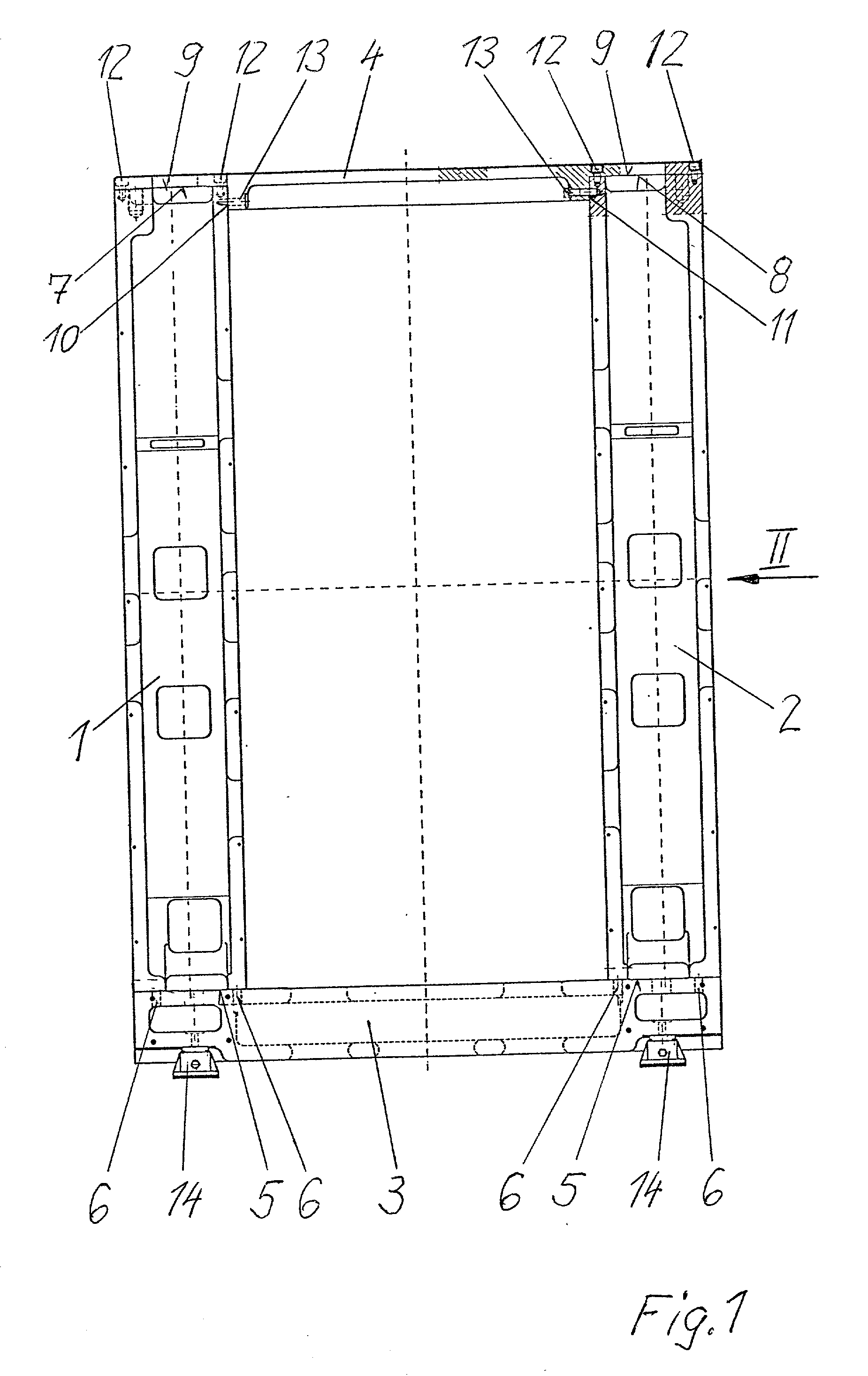
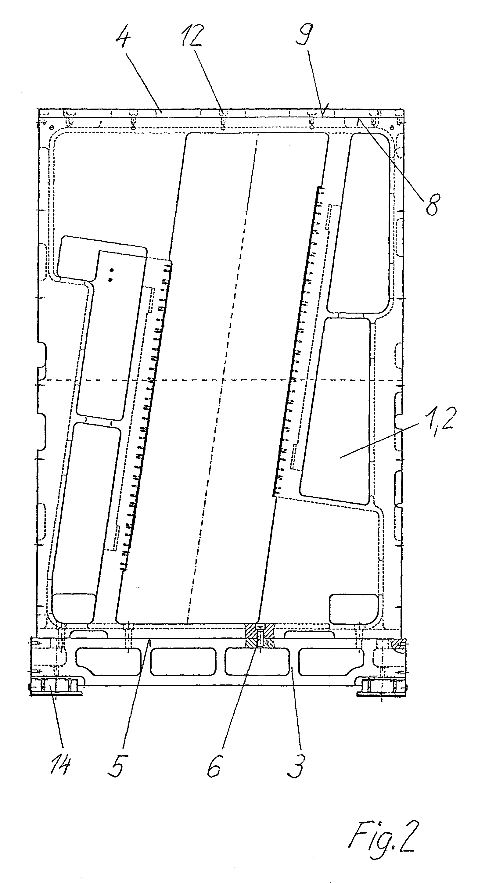
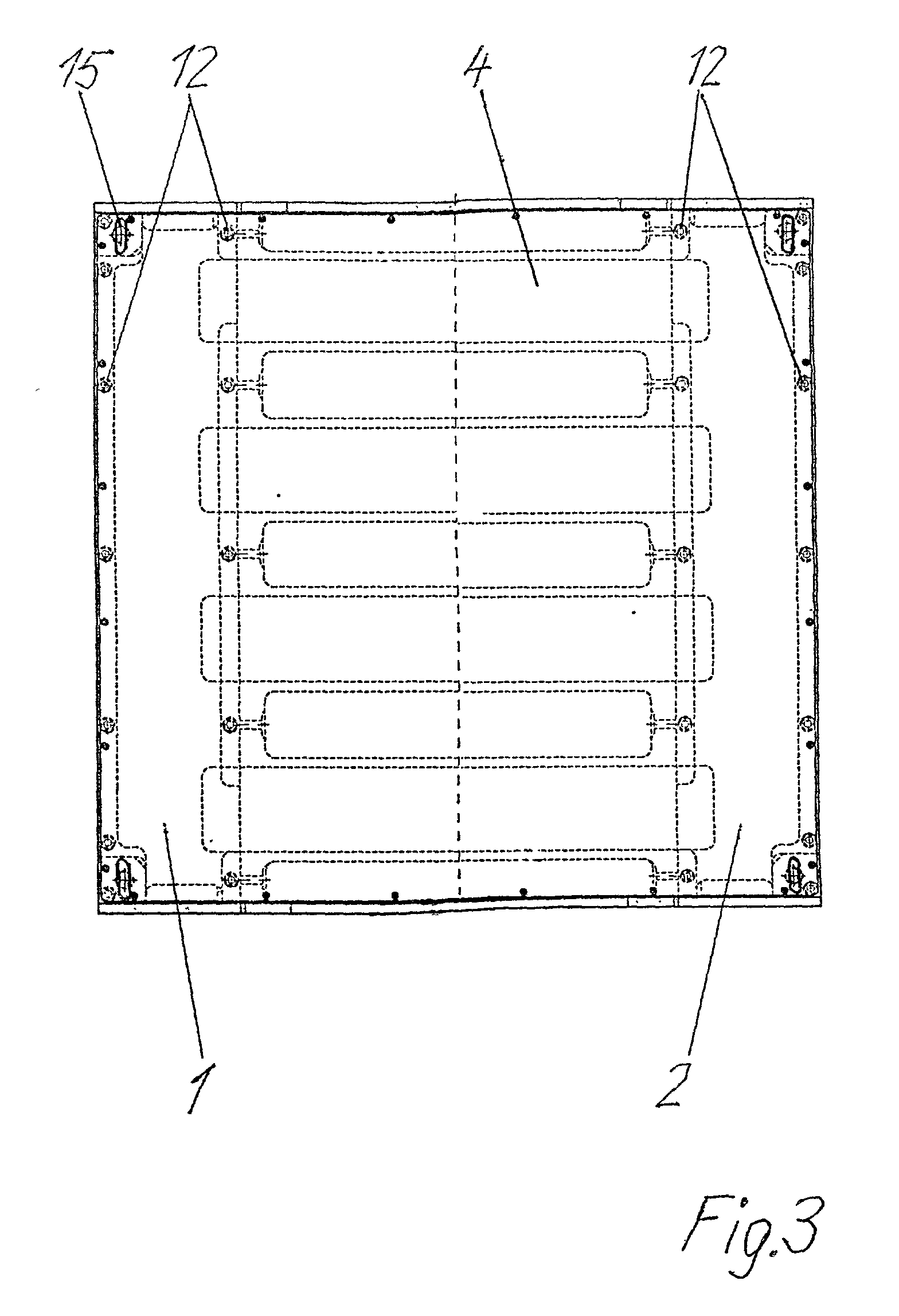
[0017] The stand, illustrated in FIGS. 1 and 2, of a printing unit of a rotary printing machine contains spaced apart left-hand and right-hand side walls 1, 2, a bottom plate 3 and a cover plate 4. The left-hand and right-hand side walls 1, 2 are each placed with a base surface 5 onto the bottom plate 3 and screwed to the latter. The screws 6 used for this purpose are arranged in the edge regions of the base surfaces 5, with the result that a high rigidity of the screw connection of the side walls 1, 2 to the base plate 3 is achieved.

[0018] The cover plate 4 lies with a left-hand first locating face 7 on the left-hand side wall 1 and with a right-hand first locating face 8 on the right-hand side wall 2, in each case on a cover surface 9. Furthermore, the cover plate 4 rests with a left-hand second locating face 10 and a right-hand second locating face 11 in each case rested against a lateral surface of the respective side walls 1, 2 and is screwed to the respecting side walls 1, 2 a...


PUM


Abstract

In order to provide a stand of a printing unit of a rotary printing machine, said stand being capable of being produced cost-effectively and having high inherent rigidity, a left-hand and a right-hand side wall are placed onto a bottom plate and screwed to the latter and are also provided with a cover plate, the cover plate resting with first locating faces on the side walls and with second locating faces against the side walls, the cover plate being screwed to the side walls at all the locating faces.

Description

[0001] 1. Field of the Invention[0002] The invention relates to a stand of a printing unit of a rotary printing machine, said stand containing a left-hand and right-hand side wall.[0003] 2. Description of the Related Art[0004] The specialized article by Schmidt, F. J. and Naumann, M.: Zur Konstruktion von Verarbeitungsmaschinen.about.Gestellen [On the Construction of Processing Machine Stands], in: Konstruktion 48 (1996) 128-136, Springer-Verlag 1996, pages 128 to 136, shows processing machine stands. These have two side walls, between which a baseplate and a plurality of crossmembers are arranged.[0005] A stand of this type is cost-intensive because of complicated mechanical machining and a relatively large number of crossmembers. An increased outlay in terms of assembly also contributes to the rise in costs. Thus, round crossmembers are inserted into the side walls, in order to orient the bores of the side walls in alignment. All these crossmembers restrict the space available bet...

Claims


Application Information

Patent Timeline
IPC IPC(8): B41F13/00
CPCB41F13/0024
Inventor GOTTLING, JOSEFPETERSEN, GODBER
Owner MANROLANAD AG
Why Eureka
Try Eureka