High rangeability control valve

a rangeability control and high range technology, applied in the direction of water supply installation, mechanical equipment, transportation and packaging, etc., can solve the problems of erosion 36, not addressing specific geometry, not allowing high rangeability, etc., and achieve the effect of reducing flow through the clearan

Inactive Publication Date: 2003-12-11
DRESSER LLC
View PDF0 Cites 36 Cited by
  • Summary
  • Abstract
  • Description
  • Claims
  • Application Information

AI Technical Summary

Benefits of technology

0021] More specifically, a control valve may be provided with a linearly movable plug positioned in a fluid flow path. The plug moves in a cage comprising a plurality of ports located axially along the cage. Thus, moving the plug will modify the rate of fluid flow. A radial clearance is defined between the cage and the plug. And a seal, comprising an elastomeric inner seal and metallic outer seal, reduces flow through the clearance. The plug defines, at least in part, a vapor recovery gallery between the plug and the cage, wherein the gallery is below the lowest port when the plug is seated. When the plug is lifted to expose, at least in part, the lowest port, the gallery is above a seat that interacts with the plug to close the valve.

Problems solved by technology

The '284 patent design does not address specific geometry for controlling the pressure recovery of the controlled fluid and it does not allow for high rangeability.
Under high-pressure drop conditions, particularly high-pressure liquid letdown (as opposed to gas), clearance flow throttling can be very damaging to metal surfaces, thereby causing erosion 36.
This will lead to full pressure drop between the non-exposed staged flow paths and the exposed flow paths (see FIG. 2).
This can ultimately lead to erosion 36 in the guide clearance 24 due to cavitation and high-velocity wear, resulting in eventual valve-clearance vibration problems.
Continued erosion will increase the guide clearance and further exacerbate vibration-related problems.

Method used


Image

  • High rangeability control valve
  • High rangeability control valve
  • High rangeability control valve

Examples


Embodiment Construction

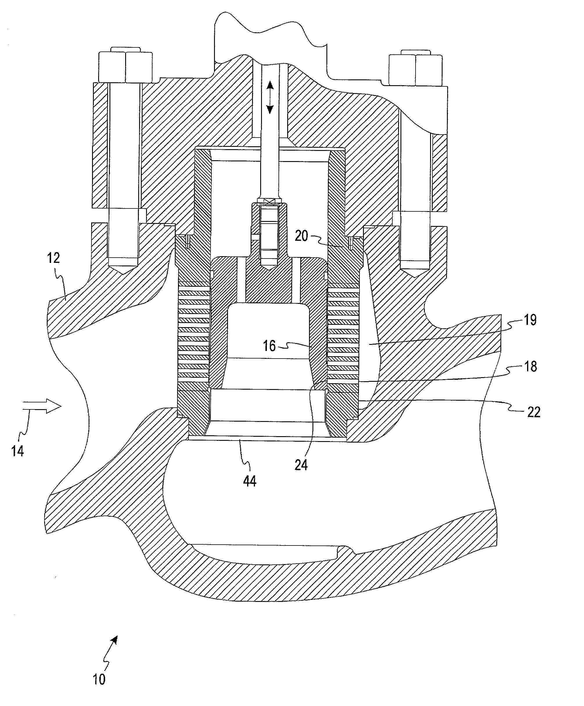
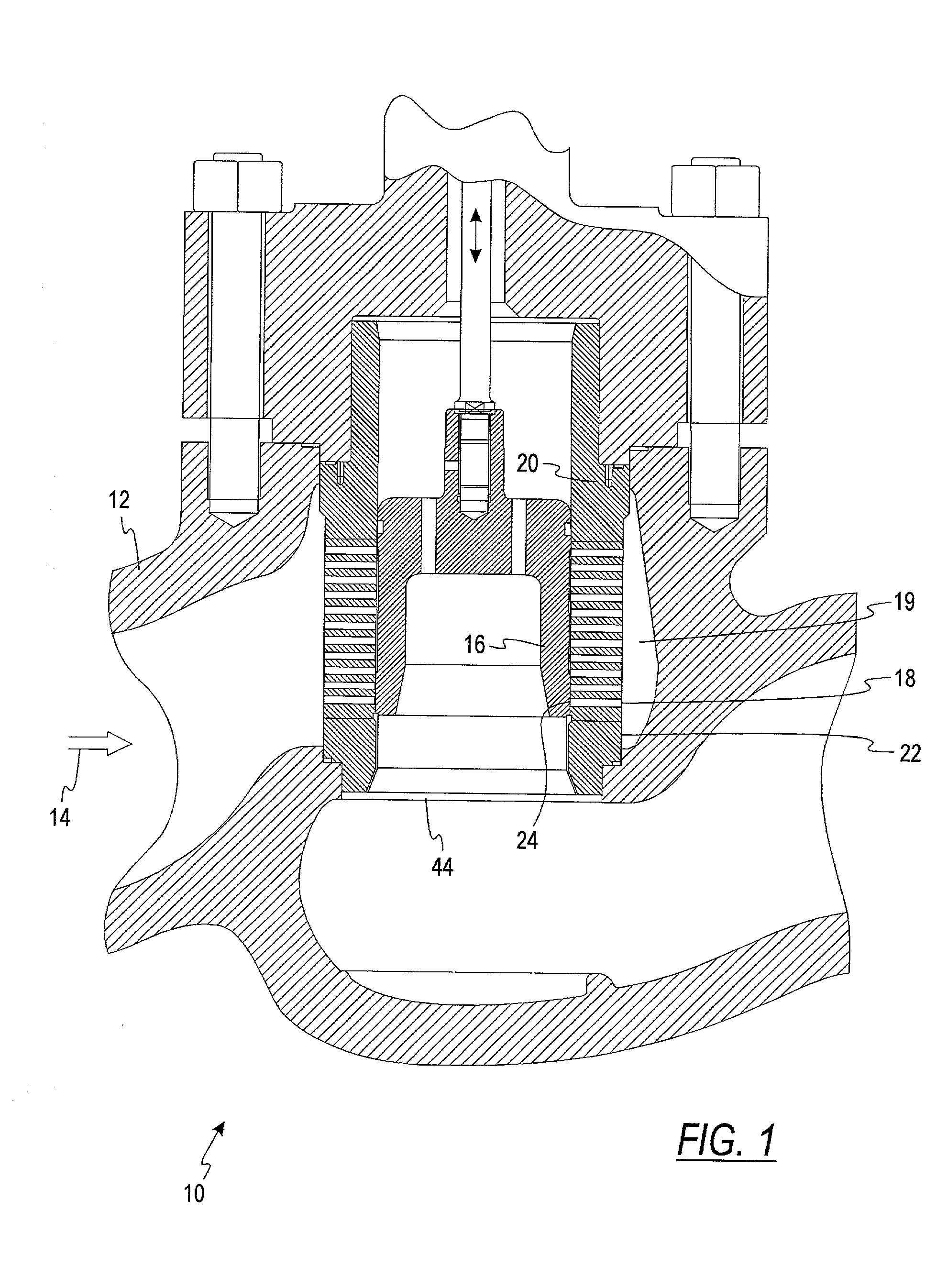
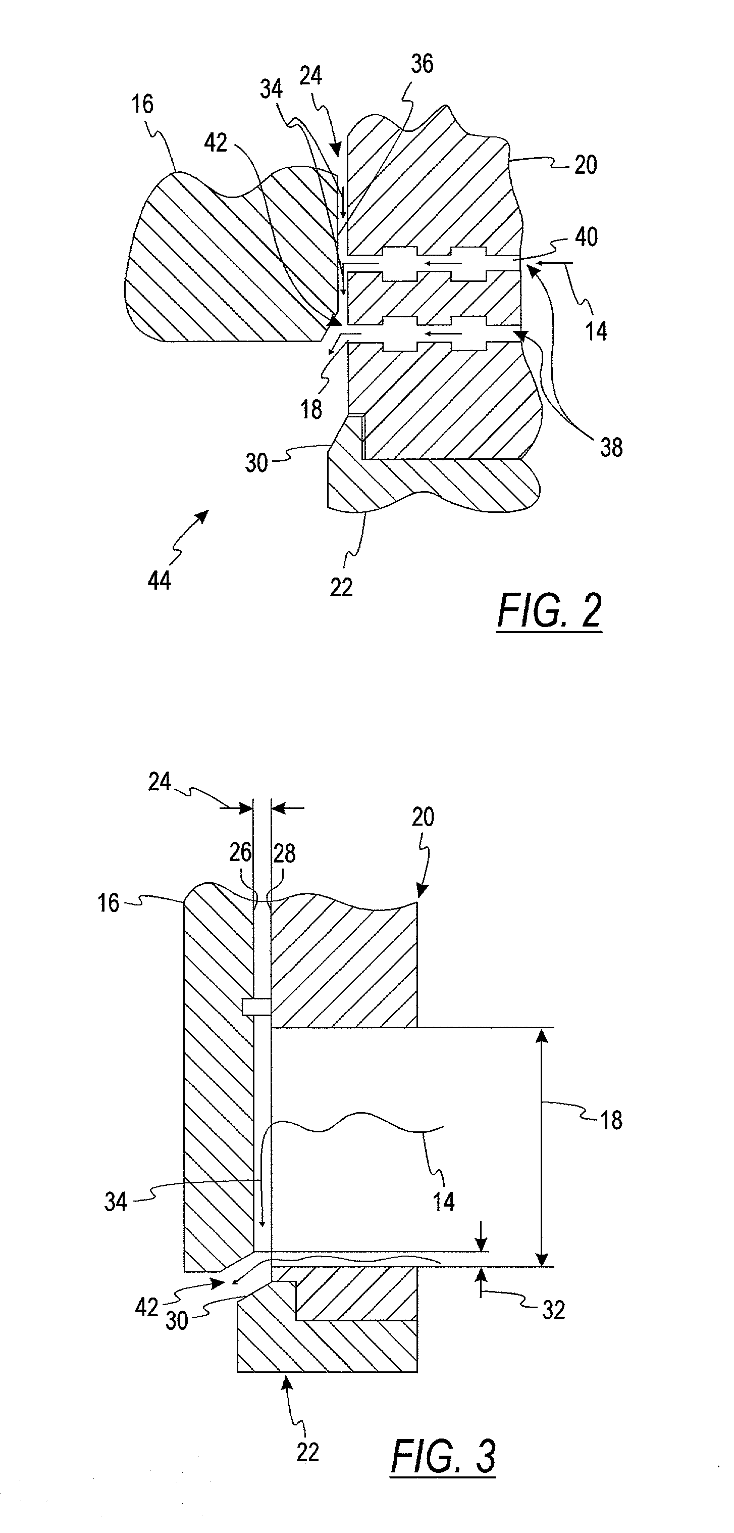
[0029] Referring to FIGS. 4 and 5, an improved cage-guided globe control valve 10' is depicted. It will be apparent from the following to those of skill in the art that the claimed invention is not restricted solely to cage-guided globe control valves. In FIGS. 4-5 a linearly movable plug 16 is positioned in a fluid flow path to modify a rate of flow, including substantially stopping the flow. Other closure members are acceptable to modify the rate of flow. A staged cage 20 aligns the plug 16. The staged cage 20 comprises a plurality of ports 18 in a port region 19 that are located axially along the cage 20. Thus, fluid flow is varied through movement of the plug 16. The plug 16 and the cage 20 define a radial clearance 24. A seating surface 30 interacts with the plug 16 to substantially stop the fluid flow 14 when the plug 16 is seated. A pressure recovery area 50, which is a gallery, i.e., cylindrical or ring-like in nature, in a preferred embodiment, is defined between the plug 1...


PUM


Abstract

A guided control valve comprising a vapor recovery area that encourages collapse of vapor bubbles. In a cage-guided valve, a seal comprising inner and outer members reduces flow through a radial clearance between a plug and a cage. The vapor recovery area is positioned below the seal and above a seat interacting with the plug. The vapor recovery area encourages collapse of vapor bubbles to reduce damage to the valve trim.

Description

[0001] This invention is directed generally to flow control valves and more specifically to cage-guided control valves.[0002] U.S. Pat. No. 4,256,284 describes a high energy loss fluid flow control device that uses a stepped-spiraled-tapered bore and control element to minimize clearance flow. The '284 patent, however, presents a clearance flow minimizing design that is physically and operationally different from the invention. The '284 patent design does not address specific geometry for controlling the pressure recovery of the controlled fluid and it does not allow for high rangeability.[0003] A typical globe valve is a valve with a linear motion closure member, one or more ports and a body typically distinguished by a globular shaped cavity around the port region. The body is the part of the valve which is the main pressure boundary. The body typically provides the pipe connecting ends and the fluid flow passageway. In a globe valve, the closure member is a movable part of the va...

Claims


Application Information

Patent Timeline
Patent Type & Authority Applications(United States)
IPC IPC(8): F16K47/02F16K3/24F16K47/08
CPCF16K47/08Y10T137/86759Y10T137/86807Y10T137/86734
Inventor STARES, JAMES A.BITTNER, CHRISTOPHER
Owner DRESSER LLC
Why Eureka
Try Eureka