Master cylinder

a master cylinder and master cylinder technology, applied in the direction of fluid couplings, couplings, braking systems, etc., can solve the problems of high cost and difficulty in providing an inexpensive master cylinder, and achieve the effect of suppressing the occurrence of squeak and rattl

Inactive Publication Date: 2005-04-21
NABLESCO CORP
View PDF4 Cites 5 Cited by
  • Summary
  • Abstract
  • Description
  • Claims
  • Application Information

AI Technical Summary

Benefits of technology

[0009] It is another object of the present invention to provide a master cylinder which is ...

Problems solved by technology

The strong coupling means leads to a higher cost, thereby...

Method used


Image

  • Master cylinder
  • Master cylinder
  • Master cylinder

Examples


Embodiment Construction

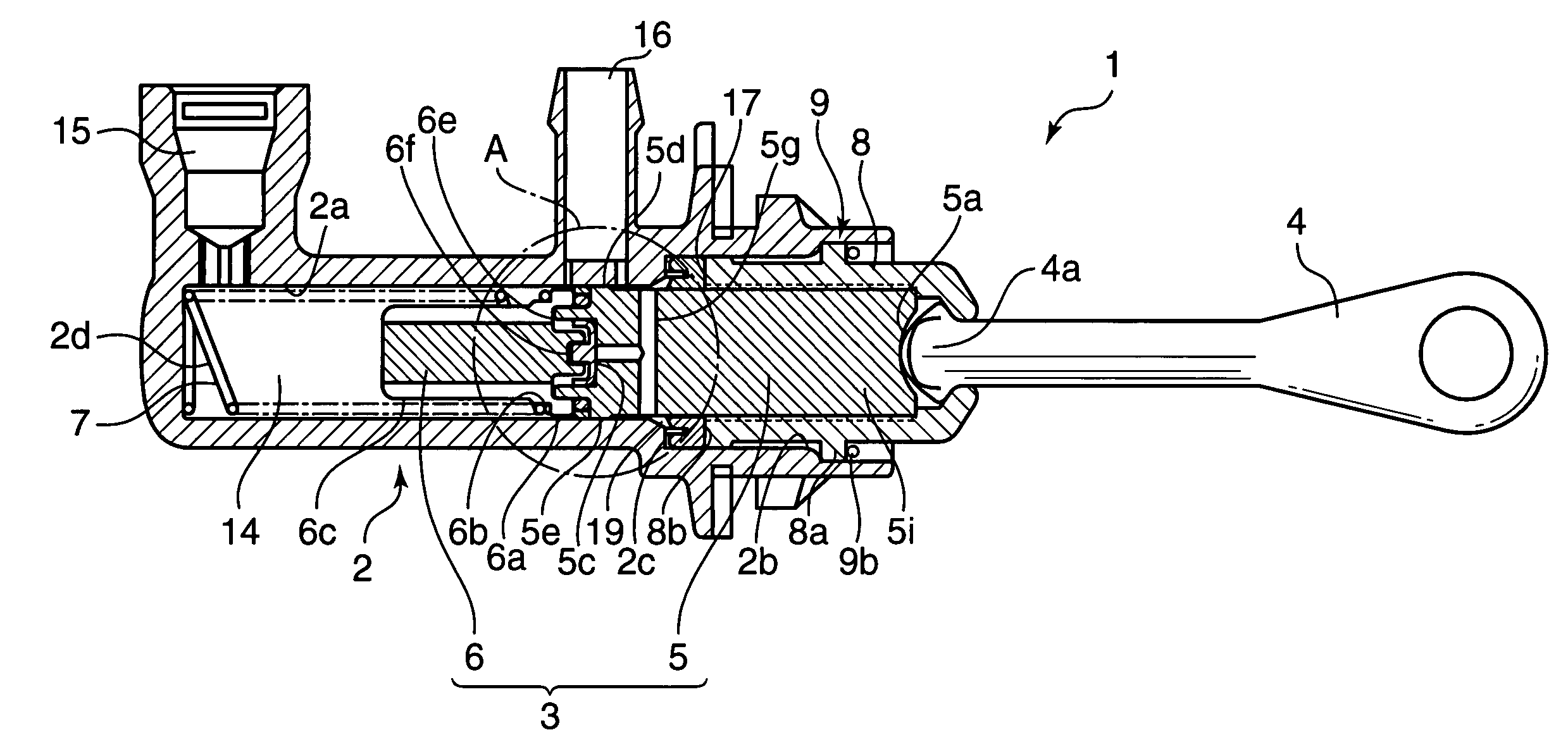
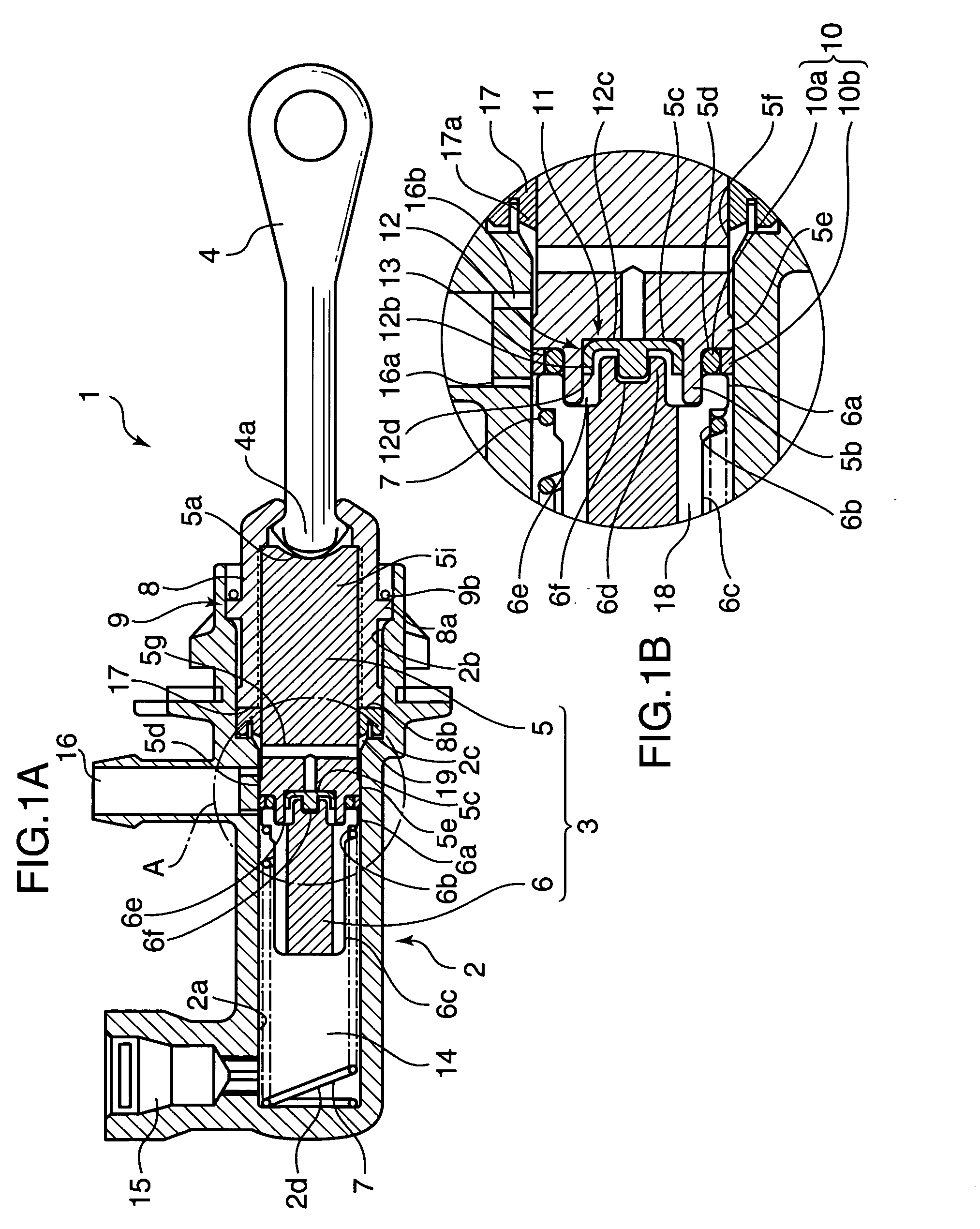
[0023] Referring to FIGS. 1A and 1B showing a construction of a master cylinder embodying the present invention, a master cylinder 1 includes a cylinder main body 2 formed with a cylinder hole 2a and a mount hole 2b concentrically continuous with the cylinder hole 2a, a guide sleeve 8 inserted into the mount hole 2b, a piston 3 which is so provided inside the cylinder hole 2a and the mount hole 2b as to be movable back and forth, a first annular sealer 10 provided on the outer circumferential surface of the piston 3, and a second annular sealer 17 provided inside the mount hole 2b of the cylinder main body 2.

[0024] In order to be lightweight, the cylinder main body 2 is made of a resin, e.g., a glass-reinforced polyamide, and the cylinder hole 2a and the mount hole 2b are formed to have round cross sections, wherein the mount hole 2b has a larger inner diameter than the cylinder hole 2a and a stepped portion 2c is formed at a boundary between the cylinder hole 2qa and the mount hol...


PUM


Abstract

A master cylinder has a resin cylinder main body formed with a step at a boundary between a cylinder hole and a mount hole. A piston cooperates with the inner circumferential surface of the cylinder hole to define a hydraulic chamber. A guide sleeve is locked in the cylinder main body and guides a base end of the piston. A first annular sealer, which has an inner seal member made of a soft material and an outer seal member made of a hard material, is held on the outer circumferential surface of a leading end of the piston. A second annular sealer is squeezed between the step and a leading end of the guide sleeve. At least a portion of the outer circumferential surface of the piston is made of a metal. The master cylinder is inexpensive and suppresses squeaks and rattles caused by the stick-slip phenomenon.

Description

BACKGROUND OF THE INVENTION [0001] 1. Field of the Invention [0002] The present invention relates to a master cylinder in which sealing is provided between an outer circumferential surface of a piston and an inner circumferential surface of a cylinder by a plurality of annular sealing members. [0003] 2. Description of the Related Art [0004] There has been known a conventional master cylinder shown in FIG. 8, e.g., in Japanese Unexamined Patent Publication No. 2000-192990. [0005] In this master cylinder, a piston 103 is provided inside a guide sleeve 102 inserted into an accommodation hole 101 formed in a cylinder main body 100, and a first annular sealer 104 and a second annular sealer 105 both made of lip packing are arranged outside the piston 103 with a spacer disk 106 provided therebetween and are so held as not to come out by the guide sleeve 102. Further, the cylinder main body 100 is made of a resin and the outer surface of the piston 103 is made of a steel. [0006] This maste...

Claims


Application Information

Patent Timeline
IPC IPC(8): B60T11/16B60T11/236F16D25/08
CPCB60T11/16B60T11/236F16J15/3228F16D2048/0212F16J15/3208F16D25/088F16D25/08F16D2025/081F16D2300/08
Inventor OKUMA, HIROSHI
Owner NABLESCO CORP
Why Eureka
Try Eureka