Electro-kinetic air transporter and conditioner devices including pin-ring electrode configurations with driver electrode

a technology of electric kinetic air transporter and driver electrode, which is applied in the direction of oxygen/ozone/oxide/hydroxide, lighting and heating apparatus, heating types, etc., and can solve the problems of reducing the collecting efficiency of the system, unsatisfactory in excess quantities, and limited extent of voltage difference increas

Inactive Publication Date: 2005-09-08
SHARPER IMAGE ACQUISTION LLC A DELAWARE LIMITED LIABILITY
View PDF99 Cites 21 Cited by
  • Summary
  • Abstract
  • Description
  • Claims
  • Application Information

AI Technical Summary

Problems solved by technology

Further, the corona discharge produced between the electrode arrays can release ozone into the ambient environment, which can eliminate odors that are entrained in the airflow, but is generally undesirable in excess quantities.
However, the extent that the voltage difference can be increased is limited because arcing will eventually occur between the collector electrodes 122 and the driver electrodes 232.
Such arcing will typically decrease the collecting efficiency of the system.
Further, the corona discharge produced between the electrode arrays can release ozone into the ambient environment, which can eliminate odors that are entrained in the airflow, but is generally undesirable in excess quantities.

Method used


Image

  • Electro-kinetic air transporter and conditioner devices including pin-ring electrode configurations with driver electrode
  • Electro-kinetic air transporter and conditioner devices including pin-ring electrode configurations with driver electrode
  • Electro-kinetic air transporter and conditioner devices including pin-ring electrode configurations with driver electrode

Examples


Embodiment Construction

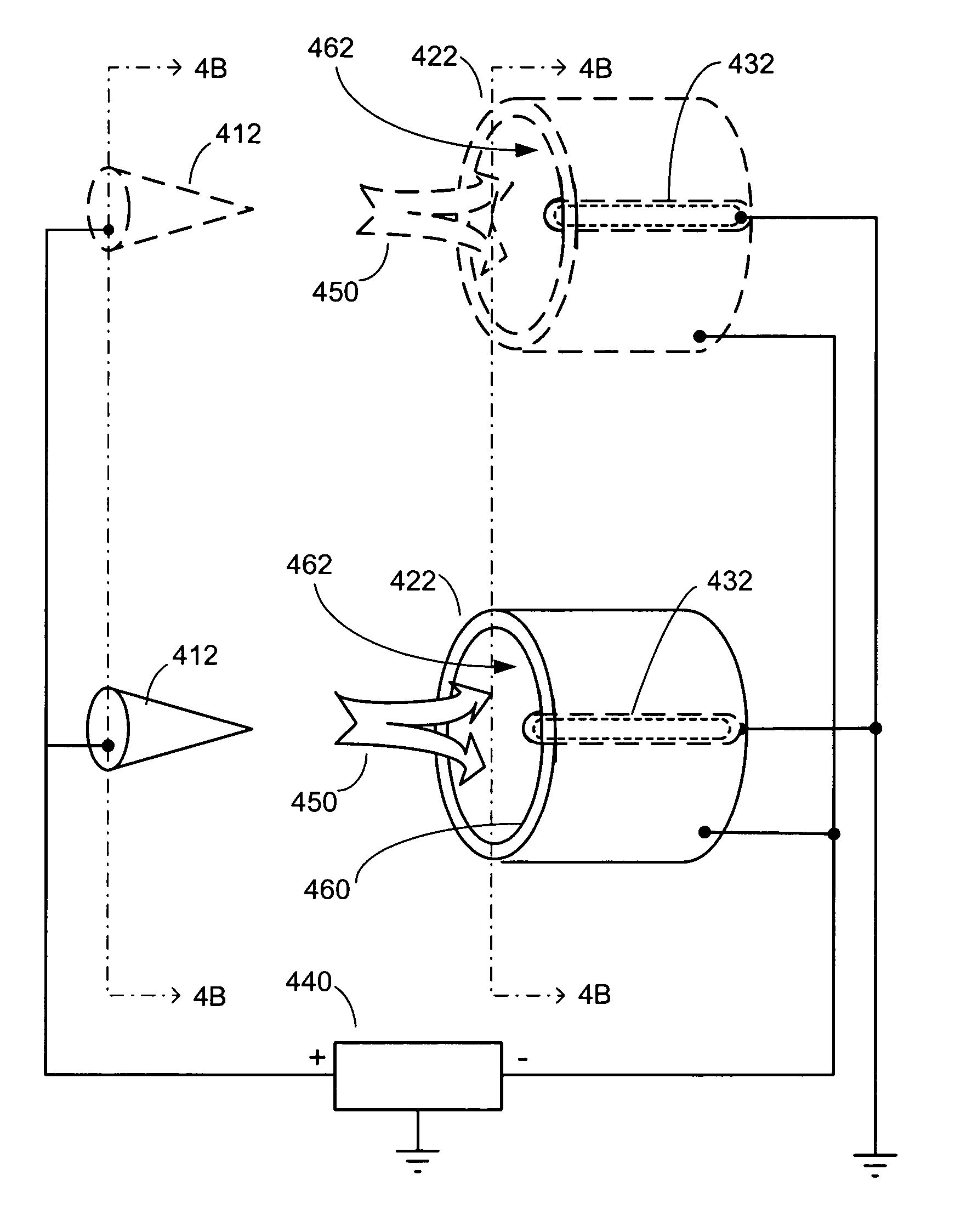
[0021] Embodiments of the present invention are related to electro-kinetic air transporter-conditioner systems and methods. In accordance with an embodiment of the present invention, a system includes at least one pin emitter electrode and at least one ring collector electrode that is downstream from the emitter electrode. A driver electrode is located within the interior of the collector electrode. Preferably, although not necessarily, the driver electrode is insulated. A high voltage source provides a voltage potential to at least one of the emitter electrode and the collector electrode to thereby provide a potential different therebetween. The driver electrode may or may not be at a same voltage potential as the emitter electrode, but should be at a different voltage potential than the collector electrode.

[0022] Insulation on the driver electrode allows the voltage potential to be increased between the driver and collector electrodes, to a voltage potential that would otherwise ...


PUM


Abstract

Electro-kinetic air transporter and conditioner systems and methods are provided. A system includes a pin emitter electrode and a ring collector electrode located downstream from the emitter electrode. A driver electrode, which is preferably insulated, is located at least partially within an interior of said ring collector electrode. A high voltage source provides a voltage potential to at least one of said emitter electrode and said collector electrode to thereby provide a potential difference therebetween. The driver electrode may or may not be at a same voltage potential as the emitter electrode, but should be at a different voltage potential than the collector electrode. This description is not intended to be a complete description of, or limit the scope of, the invention. Other features, aspects, and objects of the invention can be obtained from a review of the specification, the figures, and the claims.

Description

CROSS-REFERENCE TO RELATED ART [0001] The present invention is related to the following patent applications and patent, each of which is incorporated herein by reference: U.S. patent application Ser. No. 10 / 717,420, filed Nov. 19, 2003, entitled “Electro-Kinetic Air Transporter and Conditioner Devices with Insulated Driver Electrodes” (Attorney Docket No. SHPR-01414US1); U.S. patent application Ser. No. 10 / 774,579, filed Feb. 9, 2004, entitled “Electrostatic Precipitators with Insulated Driver Electrodes” (Attorney Docket No. SHPR-01436US0); U.S. patent application Ser. No. 10 / 074,207, filed Feb. 12, 2002, entitled “Electro-Kinetic Air Transporter-Conditioner Devices with Interstitial Electrodes” (Attorney Docket No. SHPR-01041USN); U.S. patent application Ser. No. 10 / 074,827, filed Feb. 12, 2002; and U.S. Pat. No. 6,176,977, entitled “Electro-Kinetic Air Transporter-Conditioner”.FIELD OF THE INVENTION [0002] The present invention relates generally to devices that electro-kineticall...

Claims


Application Information

Patent Timeline
Patent Type & Authority Applications(United States)
IPC IPC(8): B01J19/08
CPCF24F3/166B03C2201/10F24F2003/1682B03C3/06B03C3/12B03C3/38B03C3/41B03C3/49B03C2201/06C01B13/11C01B2201/14C01B2201/22C01B2201/62C01B2201/80B03C2201/14F24F8/192F24F8/30Y02A50/20
Inventor BOTVINNIK, IGOR Y.PARKER, ANDREW J.TAYLOR, CHARLES E.
Owner SHARPER IMAGE ACQUISTION LLC A DELAWARE LIMITED LIABILITY
Why Eureka
Try Eureka