Tire valve-gauge combination

a valve stem and combination technology, applied in the field of accessories, can solve the problems of not having the flexibility necessary for the abuse taken by the valve stem, failing to provide the required flexibility to resist breakage, and affecting the accuracy of the valve stem, etc., to achieve the effect of flexibility, accuracy and durability

Inactive Publication Date: 2005-10-06
COUSINEAU WILLIAM
View PDF9 Cites 10 Cited by
  • Summary
  • Abstract
  • Description
  • Claims
  • Application Information

AI Technical Summary

Benefits of technology

[0009] It is thus the object of the present invention to provide vehicle operators with a combination a

Problems solved by technology

However, some of these inventions either did not work or failed to have the flexibility necessary for the abuse taken by valve stems.
It is common for drivers to utilize an accessory tire gauge, which requires the removal of the valve stem cover, thereby soiling the driver's fingers in doing so.
Additionally, in a worst-case event, if a combination valve becomes severely damaged, the combination valve would be required to maintain tire pressure at any cost.
However, this device fails to provide the required flexibility to resist breakage from the day to day abuse imposed onto the device.
Ho

Method used


Image

  • Tire valve-gauge combination
  • Tire valve-gauge combination
  • Tire valve-gauge combination

Examples


Embodiment Construction

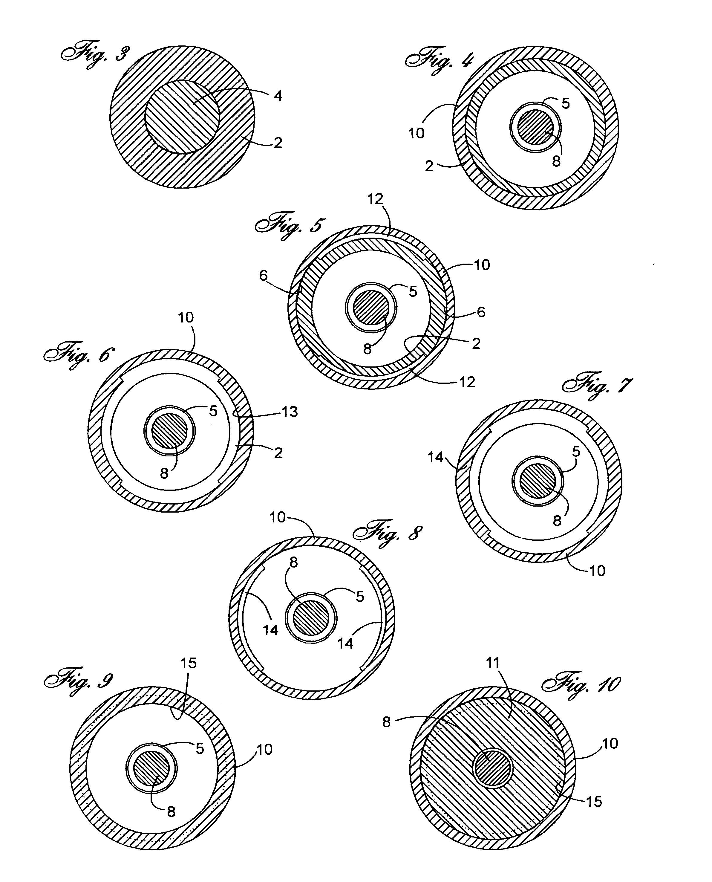
[0025] In the following description, similar features in the drawings have been given similar reference numerals.

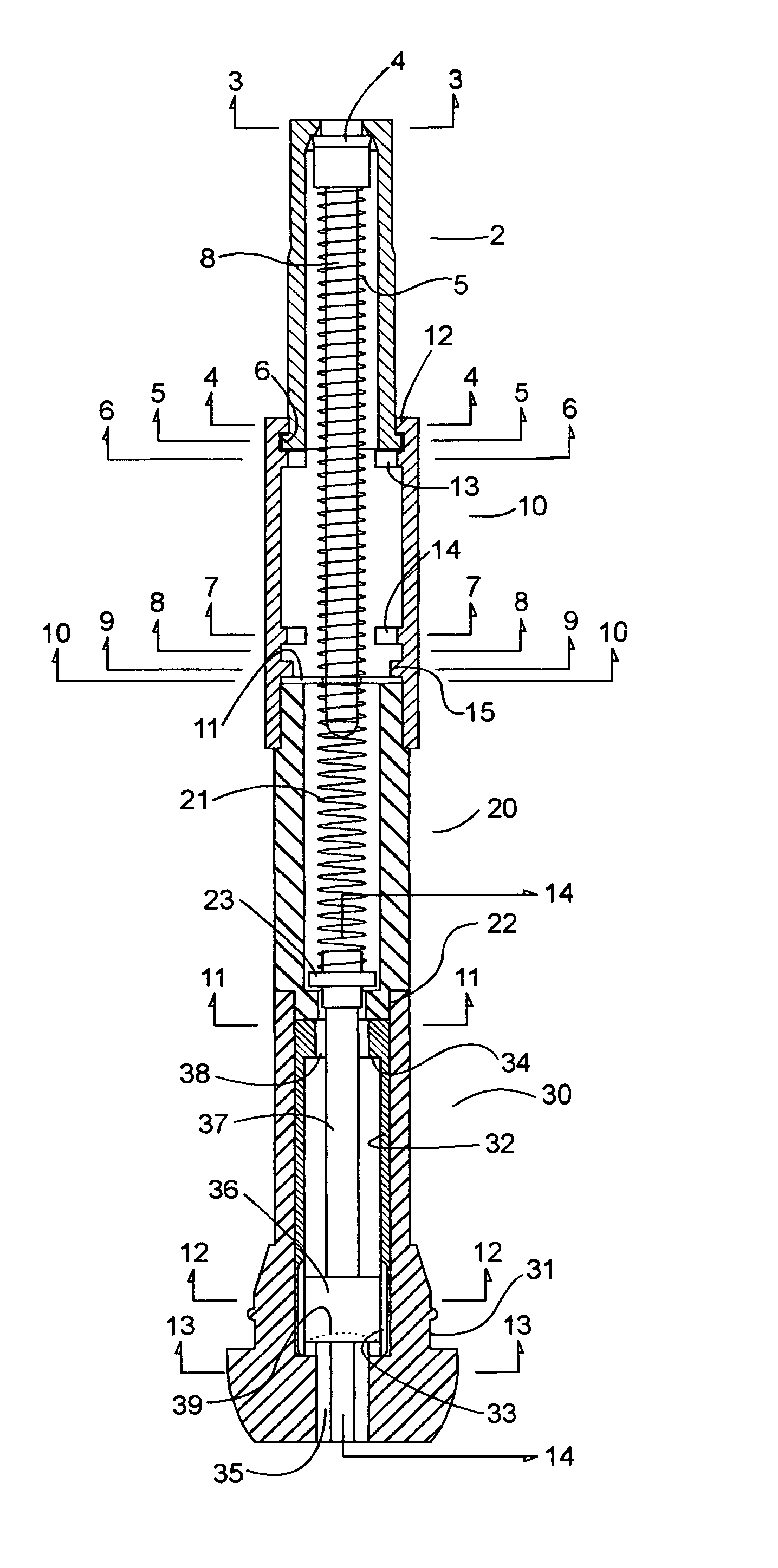
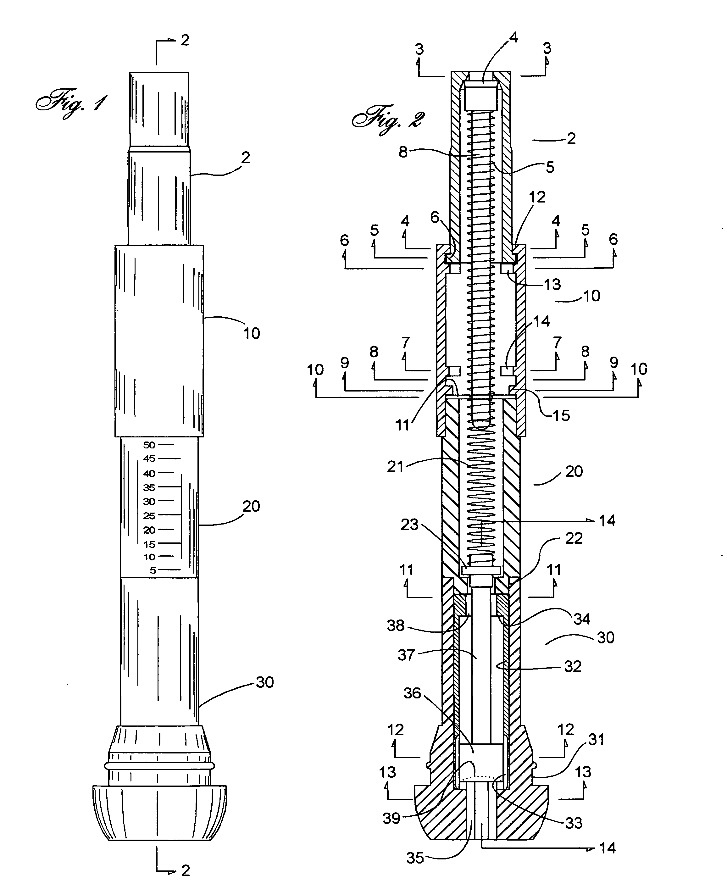
[0026] Turning to FIG. 1, which illustrates the arrangement of the various components forming part of the present invention comprising generally: a base portion 30, a gauge portion 20, a cap base portion 10 and a cap 2 wherein the base 30 is fabricated of a resilient rubber-like material having a lower body portion larger than the valve perforation of a conventional tire rim and a central neck portion having an outside diameter equal or lesser than said rim perforation, the gauge portion 20 fabricated of a clear rigid material having imprinted markings identifying the location of a longitudinally moveable indicator adapted to travel within said gauge portion, the cap base portion 10 is adapted to securedly attach to the upper portion of the gauge portion 20 and slidably communicating with a cap portion 2.

[0027] Turning to FIG. 2, illustrating a cross-section view taken ...


PUM


Abstract

A tire valve-gauge combination utilized to inflate and deflate conventional tubed or tubeless tires while giving the user an indication of the amount of air pressure within the tire's chamber. The accessory device of the present invention comprises; a flexible rim-attaching base having a larger lower body portion than the rim perforation of a conventional tire and a central neck portion having an outside diameter equal or lesser than said rim perforation, a rigid gauge portion having a transparent molded tube-like form imprinted with markings identifying the location of a moveable luminescent indicator adapted to travel longitudinally within said gauge portion, a cap base portion adapted to securedly attach to the upper portion of the gauge portion and slidably communicating with a cap portion. Therefore, when a tire is under pressure, the inner air pressure exerts positive pressure against the under side of the piston, which in turn, displaces the location of said indicator, indicating the tire's air pressure.

Description

FIELD OF THE INVENTION [0001] The present invention relates to an accessory device utilized to inflate and deflate conventional tubed or tubeless tires while giving the user an indication of the amount of air pressure within the tire's chamber. The accessory device of the present invention comprises; a flexible rim-attaching base having a larger lower body portion than the rim perforation of a conventional tire and a central neck portion having an outside diameter equal or lesser than said rim perforation, a rigid gauge portion having a transparent molded tube-like form imprinted with markings identifying the location of a moveable luminescent indicator adapted to travel longitudinally within said gauge portion, a cap base portion adapted to securedly attach to the upper portion of the gauge portion and slidably communicating with a cap portion. Therefore, when a tire is under pressure, the inner air pressure exerts positive pressure against the under side of the piston, which in tu...

Claims


Application Information

Patent Timeline
IPC IPC(8): B60C23/00B60C23/02B67D7/22
CPCB60C23/0496Y10T137/36
Inventor COUSINEAU, WILLIAM
Owner COUSINEAU WILLIAM
Why Eureka
Try Eureka