Paintball gun and method

a paint ball gun and paint ball technology, applied in the field of paint ball guns and methods, can solve the problems of inability to operate paint ball guns in full-automatic mode, inability to engage and release mechanical hammer and sear, and inability to use conventional paint ball guns, etc., to achieve the effect of reducing or eliminating at least on

Inactive Publication Date: 2005-10-06
BYRNE KIMBERLY
View PDF1 Cites 13 Cited by
  • Summary
  • Abstract
  • Description
  • Claims
  • Application Information

AI Technical Summary

Benefits of technology

[0010] In view of the deficiencies of the related art, it is an object f...

Problems solved by technology

However, a common problem with the conventional electro-pneumatic paint ball guns is that they use a mechanical sear device to release a hammer.
The adjustment of the engagement and release of the mechanical hammer and sear remains an uncertain element of conventional paint ball gun operation, requiring frequent adjustments in order to operate at high cyclic rates.
Further, a deficiency of conventional paint ball guns becomes apparent when...

Method used


Image

  • Paintball gun and method
  • Paintball gun and method
  • Paintball gun and method

Examples


first embodiment

[0037] Turning now to FIGS. 4-6, and FIG. 4A, an alternative embodiment of the invention is depicted. In order to obtain reference numerals for use in describing this alternative embodiment of the invention, features which are the same as or analogous to those depicted and described by reference to the invention are indicated on FIGS. 4-6 and 4A with the same reference numeral used above, and increased by one-hundred (100).

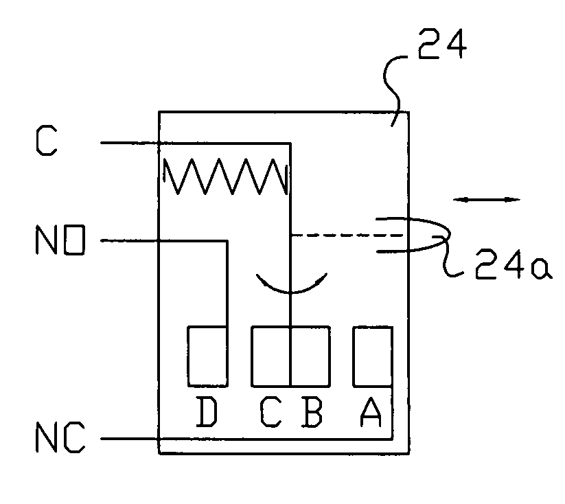
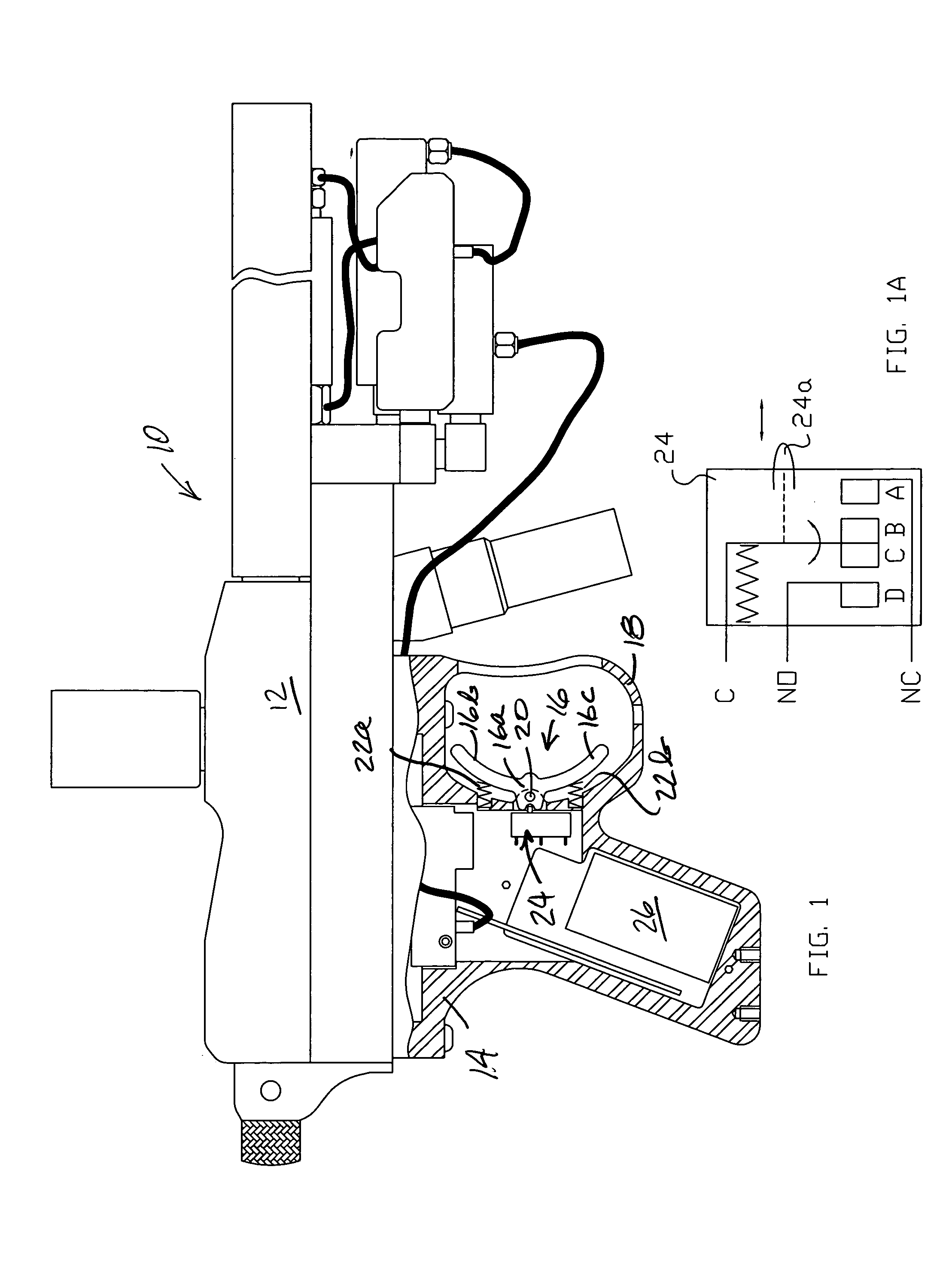
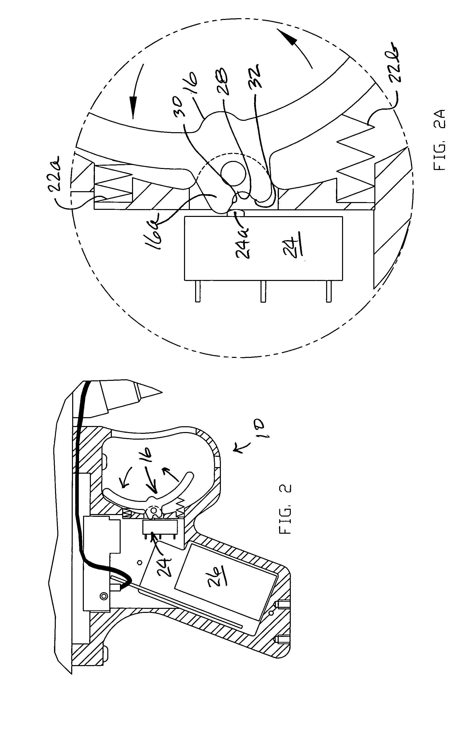
[0038] Considering now FIGS. 4-6, and FIG. 4A, in conjunction with one another a paint ball gun 110 with an inventive rocking trigger apparatus is depicted. This paint ball gun 110 includes a main body 112, with a grip frame 114 carrying a center-pivot or rocking trigger 116 shielded within a trigger guard 118. Considering the rocking trigger 116 it is seen that this trigger defines a boss 116a pivotally connected both physically and electrically by a pin 120 to the grip frame 114. In this embodiment, the trigger 116 is yieldably centered in the position seen in F...

second embodiment

[0042] Turning now to FIGS. 7-9 yet another alternative embodiment of the invention is depicted. In order to obtain reference numerals for use in describing this third alternative embodiment of the invention, features which are the same as or analogous to those depicted and described by reference to the first or second embodiment of the invention are indicated on FIGS. 7-9 with the same reference numeral used above, and increased by two-hundred (200).

[0043] Considering now FIGS. 7-9 in conjunction with one another, a paint ball gun 210 with an inventive double trigger arrangement is depicted. This paint ball gun 210 includes a main body 212, with a grip frame 214 carrying a pair of oppositely-pivoted triggers 216a and 216b, both shielded within a trigger guard 218. Considering the pair of oppositely-pivoted triggers 216a and 216b it is seen that these triggers each define one of a respective pair of boss portions 216a′ and 216b′ pivotally connected by a respective pin 220a and 220b ...

third embodiment

[0045] Turning now to FIGS. 10-12, and FIG. 10A, yet another (or fourth) alternative embodiment of the invention is depicted. In order to obtain reference numerals for use in describing this fourth alternative embodiment of the invention, features which are the same as or analogous to those depicted and described by reference to the first, second, or third embodiment of the invention are indicated on FIGS. 10-12, and FIG. 10A with the same reference numeral first used above, and increased by three-hundred (300).

[0046] Considering now FIGS. 10-12, and FIG. 10A in conjunction with one another, a paint ball gun 310 with an inventive double trigger arrangement is depicted. This paint ball gun 310 includes a main body 312, with a grip frame 314 carrying a pair of commonly-pivoted triggers 316a and 316b, both shielded within a trigger guard 318. Considering the pair of commonly-pivoted triggers 316a and 316b it is seen that these triggers each define a respective a boss portion 316a′ and ...


PUM


Abstract

A paintball gun provides a double-acting trigger apparatus including a pair of finger engagement surfaces against which a user of the gun may employ a pair of trigger fingers. The user of the paintball gun may effect a firing operation of the gun by using either one of the two fingers to pull the trigger. Consequently, rapid firing operations of the gun are effected by dithering the two trigger fingers in rapid alternating motions to apply pressure on and off the two trigger engagement surfaces. Further, the paintball gun includes a programmable, microprocessor-based controller allowing the gun to be fired in response to a chosen discreet event in time. This chosen discreet event may include the opening and/or closing of a pair of switch contacts, for example; or the making or breaking of an electrical circuit effected between conductive components of the paintball gun. Movements of the double-acting trigger apparatus will result in plural discreet events separated in time, so that plural rapid-sequence firing operations of the paintball gun may be accomplished. Accordingly, a very high cyclic rate of fire is possible with a semi-automatic paint ball gun according to this invention.

Description

CROSS REFERENCE TO RELATED APPLICATION [0001] This application is a Continuation-in-Part of U.S. application Ser. No. 10 / 965,599, filed 14 Oct. 2004, which is a Continuation of U.S. application Ser. No. 10 / 452,670, filed 30 May 2003, now U.S. Pat. No. ______ issued ______, and the disclosure of which is hereby incorporated by reference to the extent necessary for a full enabling disclosure of this present invention.FIELD OF THE INVENTION [0002] The present invention relates to a paint ball gun and method. More particularly, this invention relates to a paint ball gun having particularly advantageous apparatus and method for discharging the gun in rapid succession. BACKGROUND OF THE INVENTION [0003] Paint ball guns were originally developed for marking uses such as forestry and cattle ranching, in which frangible projectiles (or paint balls, as they are more commonly called) were fired against trees to be harvested or onto cattle to be taken to market, for example. For this reason, th...

Claims


Application Information

Patent Timeline
IPC IPC(8): F41A7/08F41A19/58F41B11/00
CPCF41A7/08F41A19/58F41B11/00F41B11/71F41B11/68F41B11/72F41B11/57
Inventor STYLES, LEON
Owner BYRNE KIMBERLY
Why Eureka
Try Eureka