Adaptive beacon period in a distributed network

Active Publication Date: 2005-11-10
PROVENANCE ASSET GRP LLC
View PDF24 Cites 81 Cited by
  • Summary
  • Abstract
  • Description
  • Claims
  • Application Information

AI Technical Summary

Benefits of technology

[0015] The present invention allows for the efficient utilization of communications resources and reduces power consumption in communications devic

Problems solved by technology

Unfortunately, because the initial MAC is inflexible in the number of beacon slots, it is likely that for any given situation, there will be either too many or too few available beacon slots.
Conversely, situations may occur where there are too many beacon slot

Method used


Image

  • Adaptive beacon period in a distributed network
  • Adaptive beacon period in a distributed network
  • Adaptive beacon period in a distributed network

Examples


Example

I. Operational Environment

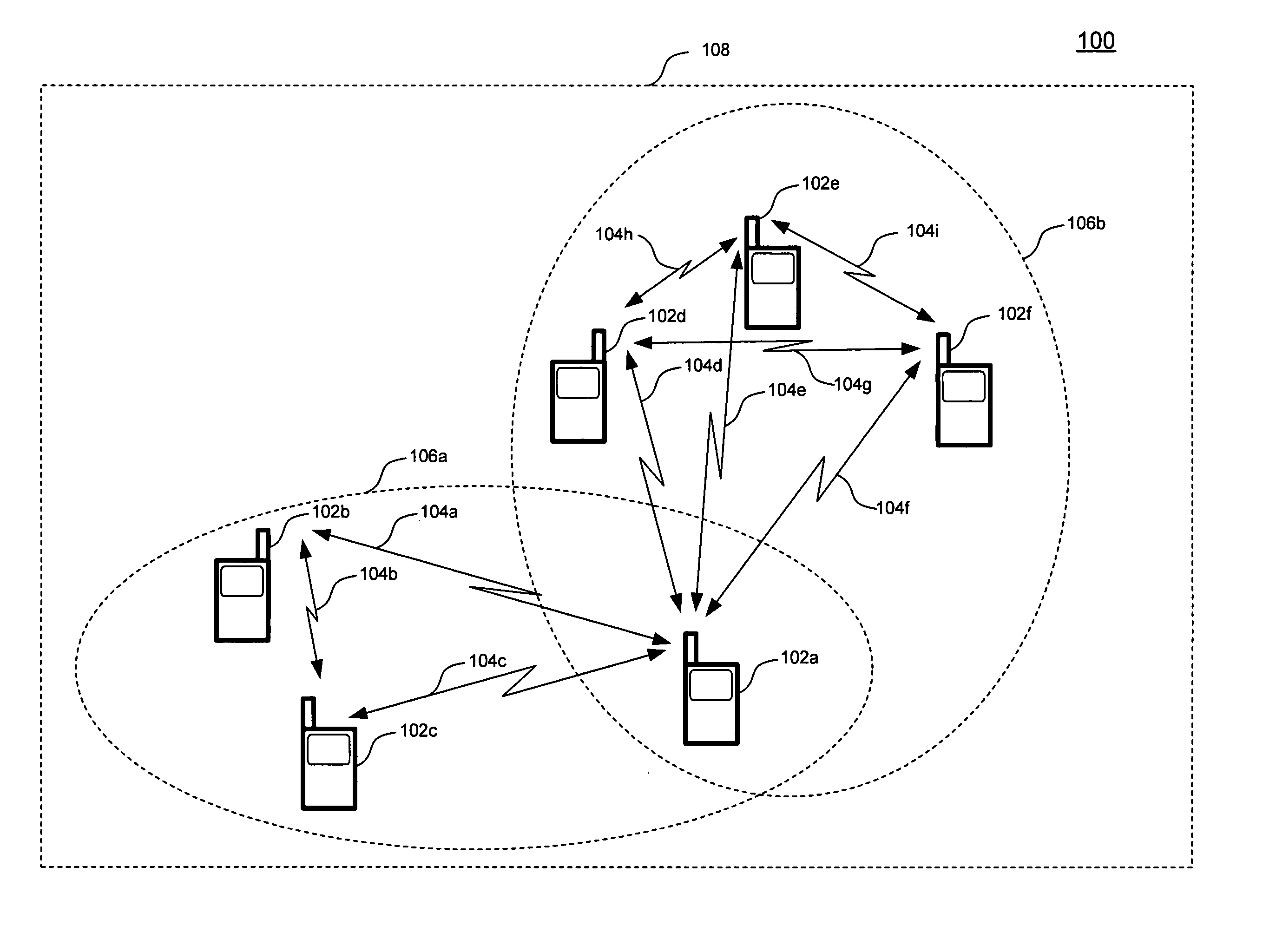
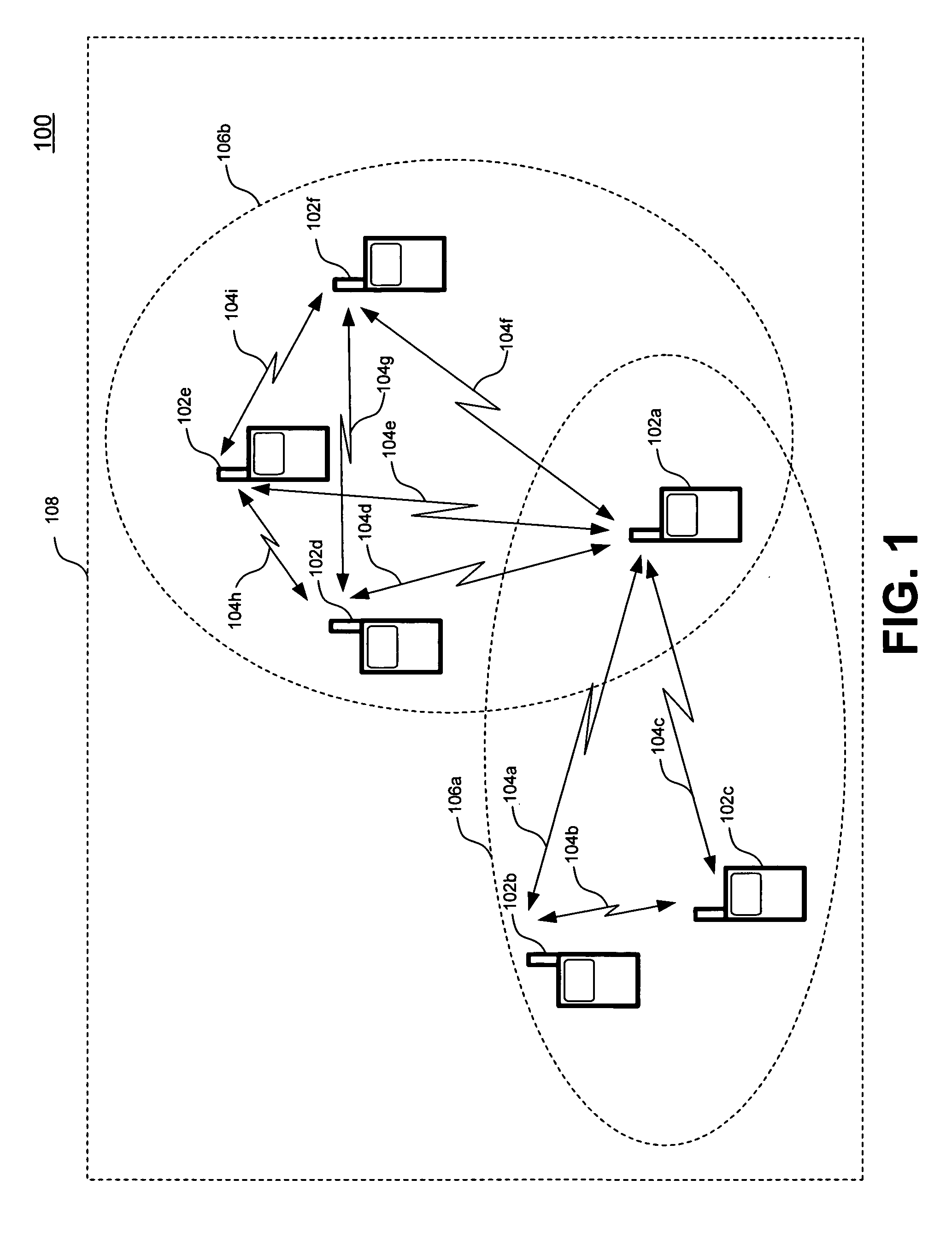
[0022] Before describing the invention in detail, it is helpful to first describe an environment in which the present invention may be used. Accordingly, FIG. 1 is a diagram of an exemplary operational environment in which the present invention may be employed. In this environment, a plurality of wireless communications devices (DEVs) 102 may exchange information with each other across a wireless personal area network (WPAN) 100. This exchange of information may occur through various communications paths or “hops”104 that exist between DEVs 102.

[0023] Network 100 includes a plurality of beaconing groups 106. Each beaconing group 106 includes a set of DEVs 102 that are within radio range of each other during a beaconing period. For instance, a beaconing group 106a includes DEVs 102a, 102b, and 102c. Also, a beaconing group 106b includes DEVs 102a, 102d, 102e, and 102f. Accordingly, DEV 102a belongs to both beaconing group 106a and 106b.

[0024] The environ...


PUM


Abstract

A wireless communications network includes one or more wireless communications devices and a wireless transmission medium. The one or more wireless communications devices transmit beacon messages across the wireless transmission medium during a beacon period that is within a superframe. The beacon period has a number of beacon slots that is dynamically adjusted.

Description

FIELD OF THE INVENTION [0001] The present invention relates to wireless communications. More particularly, the present invention relates to the allocation of resources in wireless communications networks. BACKGROUND OF THE INVENTION [0002] Short-range wireless proximity networks typically involve devices that have a communications range of one hundred meters or less. To provide communications over long distances, these proximity networks often interface with other networks. For example, short-range networks may interface with cellular networks, wireline telecommunications networks, and the Internet. [0003] IEEE 802.15.3 defines an ad hoc wireless short-range network (referred to as a piconet) in which a plurality of devices may communicate with each other. The timing of piconets is based on a repeating pattern of “superframes” in which the network devices may be allocated communications resources. Currently, the MultiBand OFDM Alliance (MBOA) is defining a media access control (MAC)...

Claims


Application Information

Patent Timeline
IPC IPC(8): H04L12/28H04L12/56H04W28/18H04W48/12H04W72/04H04W74/04H04W84/18
CPCH04W28/18H04W48/12H04W84/18H04W74/04H04W72/0406H04W72/20H04B7/26
Inventor SALOKANNEL, JUHAREUNAMAKI, JUKKA
Owner PROVENANCE ASSET GRP LLC
Why Eureka
Try Eureka