

Biopsy devices and methods
- Summary
- Abstract
- Description
- Claims
- Application Information
AI Technical Summary
Benefits of technology
Problems solved by technology
Method used
Image


Examples
Embodiment Construction
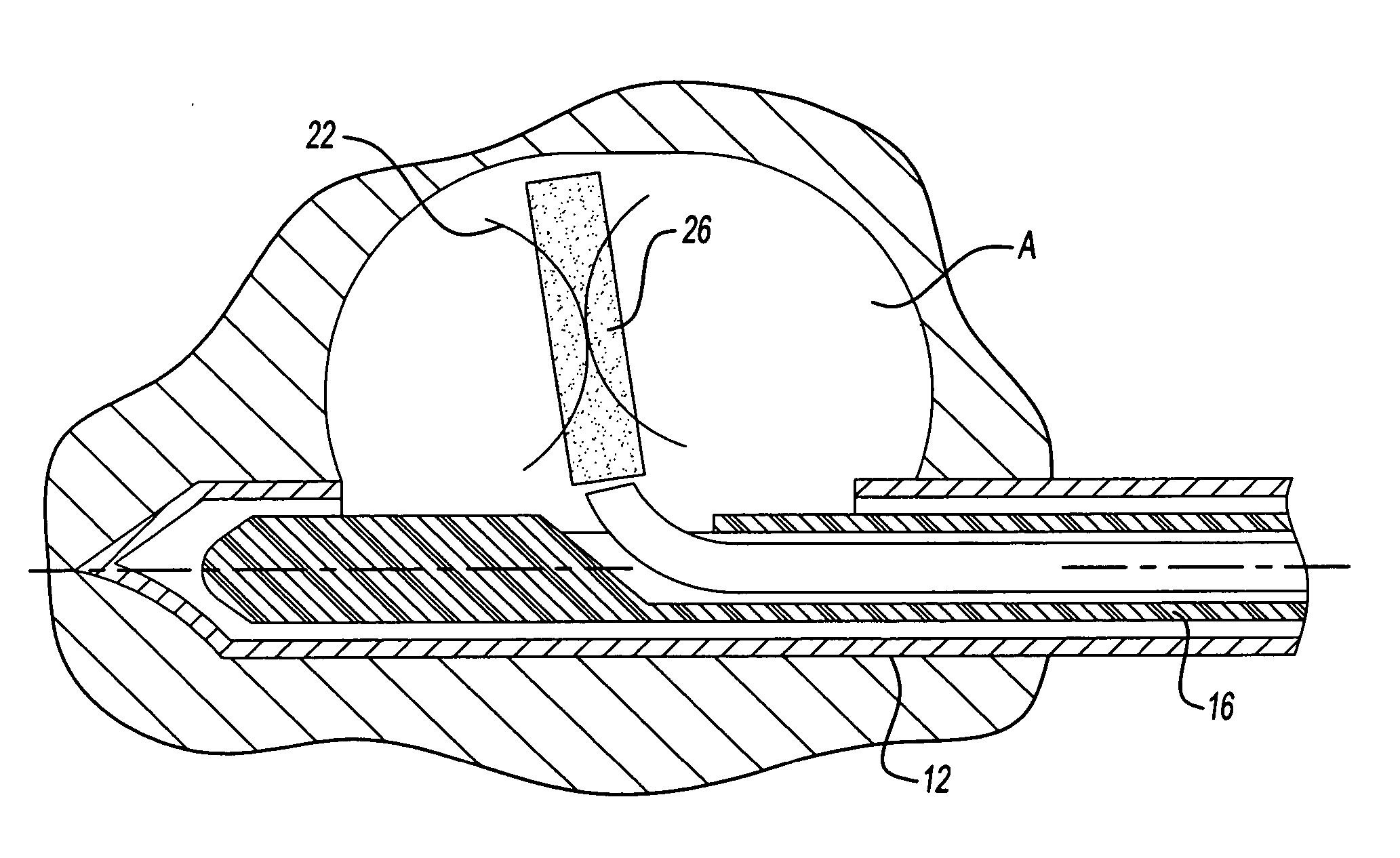
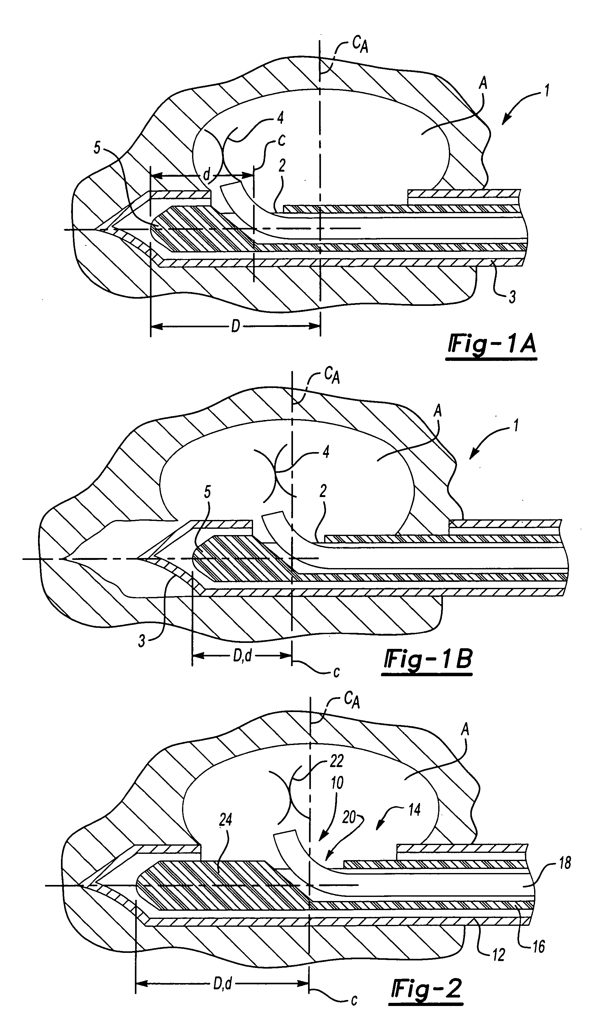
[0022] The present invention provides improved devices and methods for the marking and treatment of tissue. Such applications may be particularly useful in conjunction with ultrasonic devices used for observing and / or monitoring specific tissue regions (e.g., breast tissue or otherwise). Such application may be advantageously used with tissue removal and aspiration devices configured for receiving a marking clip deployment device.
[0023] In one application, the present invention provides a clip delivery device and method for placement of a clip at a specified tissue region of interest. The device is configured for deployment of a clip at the specific region without undue manipulation of the device within the tissue. This is particularly useful in conjunction with an aspirating and / or tissue removal device, formed in part by a hollow needle, wherein the delivery device is placed within the needle and is configured for deployment of a clip through a side portion of the device and need...
PUM
 Abstract
Description
Claims
Application Information