System and method for hub and spoke virtual private network

a virtual private network and hub technology, applied in the field of virtual private network, can solve the problems of inability of service providers to engineer the underlying network supporting vpns, inability to engineer the network support of vpns, and inability to meet the needs of vpn service providers

Inactive Publication Date: 2006-02-09
RPX CLEARINGHOUSE
View PDF5 Cites 58 Cited by
  • Summary
  • Abstract
  • Description
  • Claims
  • Application Information

AI Technical Summary

Benefits of technology

[0011] The present invention addresses the deficiencies of the art in respect to virtual private networks and, in particular, to virtual private networks which are not implemented in a manner which is engineerable and scalable as to allow network characteristics to be deterministic and understandable.

Problems solved by technology

While simple in principle, VPN service providers face myriad problems when trying to implement and support customer VPNs, particularly in the area of designing the network to meet the committed information rate (“CIR”) typically guaranteed to subscribers.
Current transmission control protocol / internet protocol (“TCP / IP”)-based VPNs suffer from a number of drawbacks which lead to inefficient and expensive implementations.
This typically results from the inability of service providers to engineer the underlying network supporting the VPNs.
The use of a connectionless “cloud” to mesh the PE devices that is completely decoupled from the contracted service connecting CE devices is inefficient, can lead to outages and over-building of the backbone network because the operation of the underlying connectionless cloud is completely decoupled from the contract load (amount of customer data) or adds moves and changes to customer sites or customer behavior.
With current RFC 2547-based implementations, the impact of customer behavior on network loading is not constrained and changes in customer behavior or addition of new customers can have unexpected effects on overall network performance.
These implementations disadvantageously (1) route traffic down the shortest weighted path and require the manual manipulation of routing algorithms to optimize network traffic distributions, (2) require operators to deal with “slosh”, i.e. bursty subscriber traffic which can result in insufficient bandwidth or too much bandwidth and (3) require engineered over-subscription (exacerbates “slosh” vulnerability to changes in subscriber behavior).
In addition, trying to offer / manage a quality of service (“QoS”) feature as part of the service provider offering for a full mesh backbone is prohibitively expensive in terms of the signaling requirements and / or the amount of backbone bandwidth which must be made available.

Method used


Image

  • System and method for hub and spoke virtual private network
  • System and method for hub and spoke virtual private network
  • System and method for hub and spoke virtual private network

Examples


Embodiment Construction

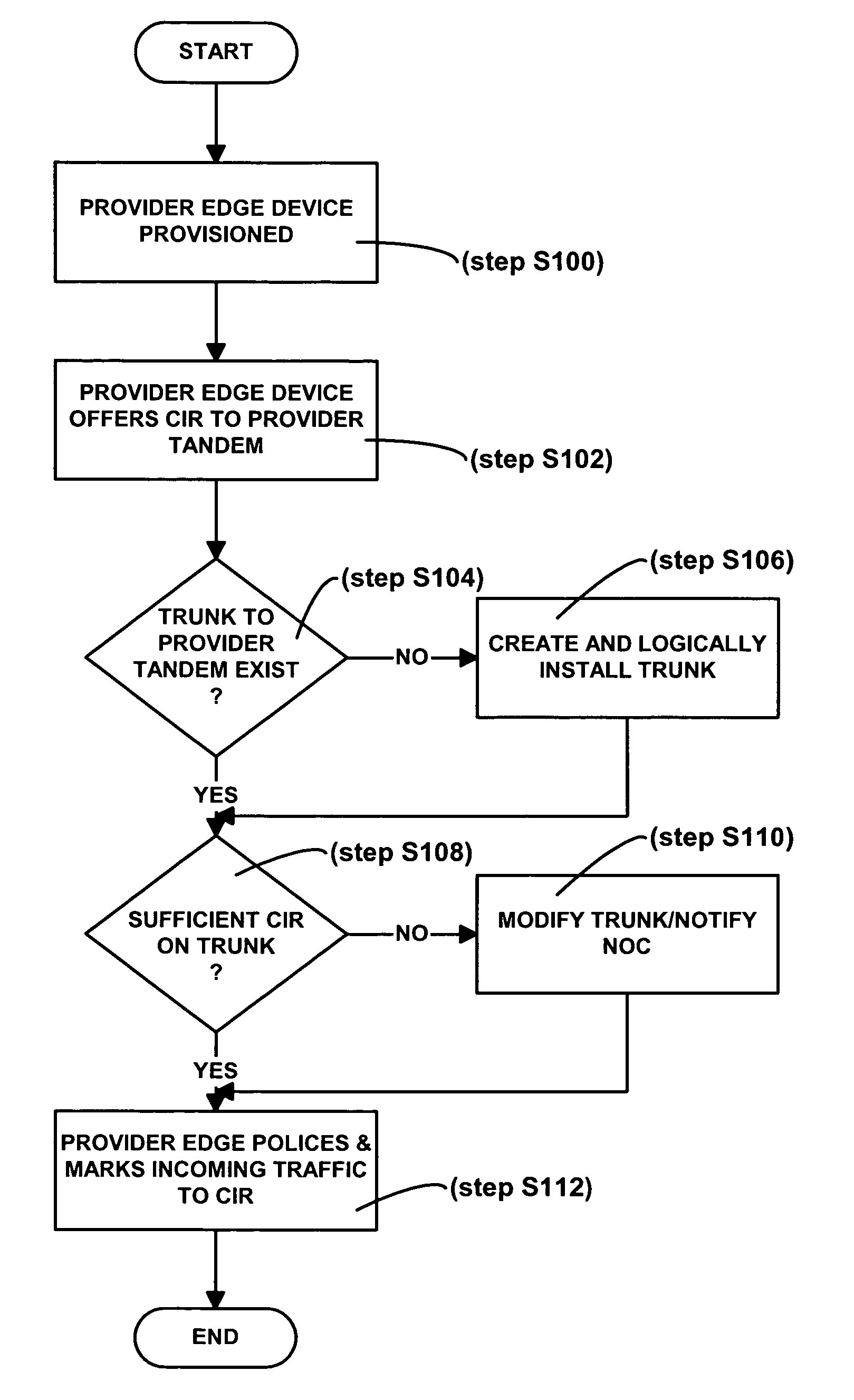
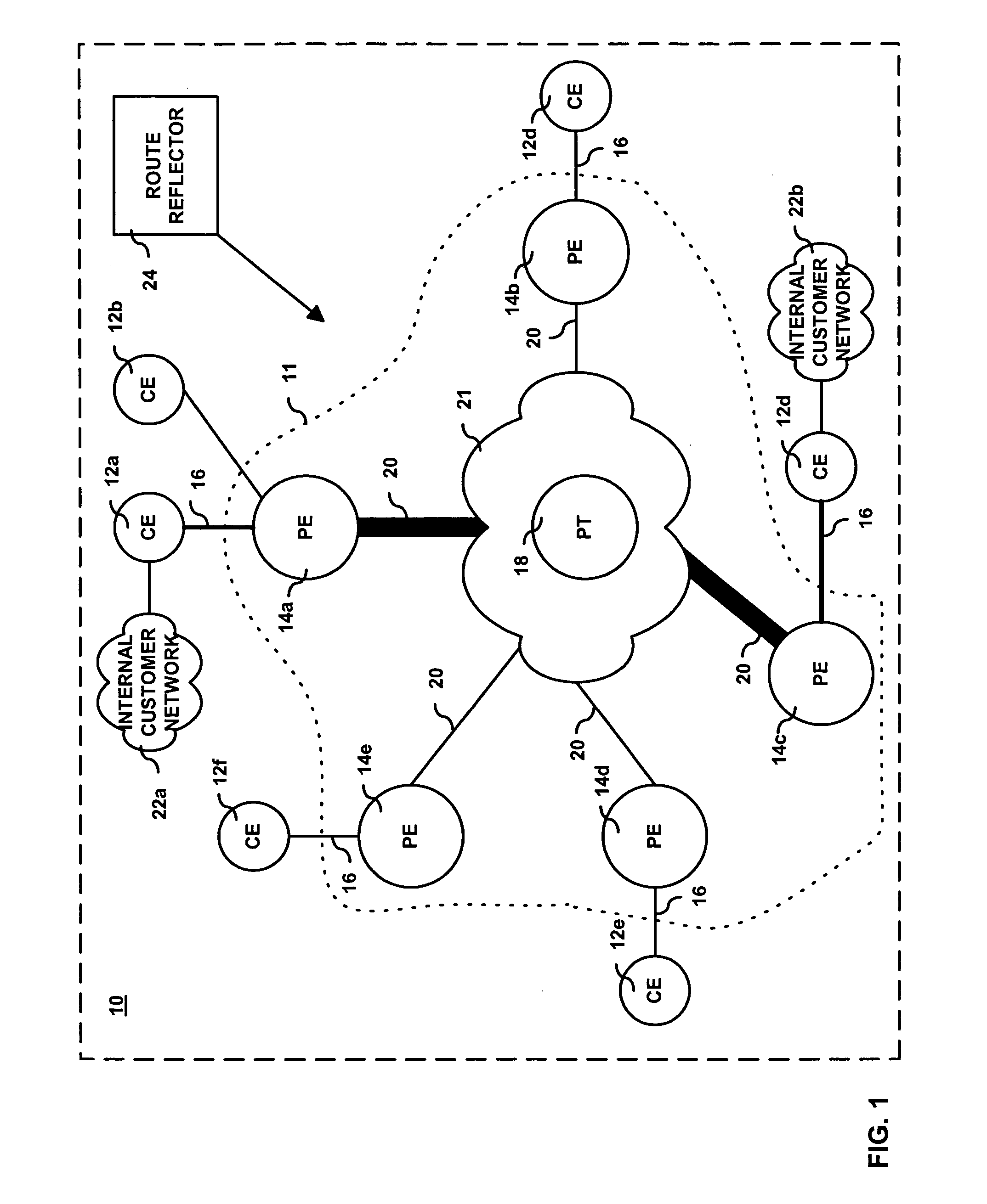
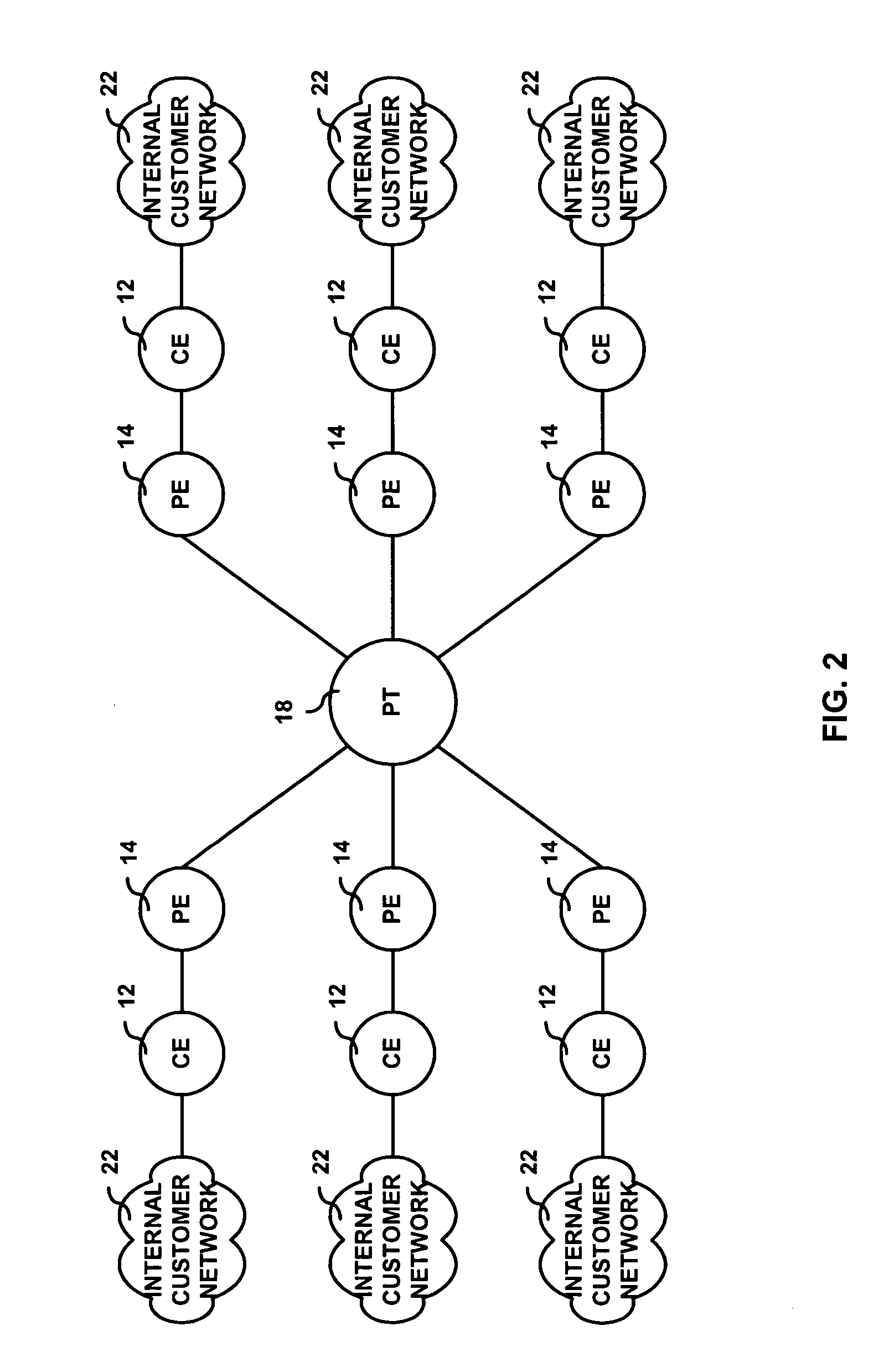
[0021] Initially, it is noted that the term “CIR” as used herein is defined to mean an indication of a contracted load for which the provisioning system explicitly allocates resources. Referring now to the drawing figures in which like reference designators refer to like elements, there is shown in FIG. 1 a diagram of a system constructed in accordance with the principles of the present invention and referred to generally as ‘10’. System 10 includes customer edge devices 12a-12f (referred collectively hereto as customer edge device 12) coupled to provider network 11, more specifically to provider edge devices 14a-14e (referred collectively hereto as provider edge device 14) via data communication link 16. Although not shown, it is contemplated that a customer edge device 12 can be linked to multiple provider edge devices 14 via multiple data communication links 16.

[0022] Customer edge devices 12 can be any routing and / or switching device as may be known in the art capable of suppor...


PUM


Abstract

A method and system for providing a virtual private communication network to transport customer data between a set of customer devices coupled to a provider network. A committed information rate is advertised to a provider tandem. The provider tandem determines whether sufficient network resources exist to successfully transport to a destination customer device all offered data from the set of customer devices.

Description

BACKGROUND OF THE INVENTION [0001] 1. Statement of the Technical Field [0002] The present invention relates to the field of virtual private networking and more particularly to a method and system for allowing an engineered virtual private networking solution through the use of a tandem routing device as a virtual hub in a logical hub and spoke network topology. [0003] 2. Description of the Related Art [0004] A virtual private network (“VPN”) allows a subscriber to use a shared networking infrastructure to provide access among the subscriber's networked devices in a manner which preserves the security and integrity of the data transmitted between the networked devices. In other words, a VPN provide remote offices or individual users for a subscribing entity with secure access to their organization's network, even though the underlying transport network is shared by many organizations. Privacy is maintained via security procedures and tunneling protocols. In effect, the tunneling prot...

Claims


Application Information

Patent Timeline
Patent Type & Authority Applications(United States)
IPC IPC(8): H04L12/28
CPCH04L12/4679H04L12/5695H04L45/04H04L45/50H04L47/15H04L47/825H04L47/724H04L47/762H04L47/781H04L47/822H04L47/20H04L47/70
Inventor ALLAN, DAVIDBRAGG, NIGELCASEY, LIAMCHIABAUT, JEROME
Owner RPX CLEARINGHOUSE
Why Eureka
Try Eureka