Transducers for focusing sonic energy in transmitting and receiving device

a technology of transducer and focusing device, which is applied in the direction of transducer details, instruments, cabinet/cabinet/drawer, etc., can solve the problems of limiting the conformity of the radiating film element to the cylindrical shape of the transducer, unable to focus sonic energy into small regions, and unable to achieve significant useful effect of sonic waves reflected from the target surface, etc., to achieve the effect of concentrating sound energy and preventing interference of sound transmission

Active Publication Date: 2006-03-16
PACKAGING TECH & INSPECTION LLC AKA PTI
View PDF10 Cites 4 Cited by
  • Summary
  • Abstract
  • Description
  • Claims
  • Application Information

AI Technical Summary

Benefits of technology

[0019] It is also an object of the present invention to provide transducers which utilize thin film radiating technology wherein the thin films are mounted relative to electrodes in such a manner as to insure that there is uniform vibration of the radiating films along the length thereof to thereby prevent interference of sound transmission and to further concentrate sound energy at a point or other well defined area.

Problems solved by technology

However, the ability of such known devices to focus sonic energy into small regions is limited because of the geometric configuration of such devices.
Because of the total area of the radiated energy from cylindrical transducer devices, most applications of such devices cause sonic waves to be reflected from a target surface without significant useful effect.
Another limiting factor of known cylindrical transducer devices is the conformity of the radiating film element to the structure of the cylindrical shape of the transducer.
Any deviation of the film radiating from the cylindrical surface can cause significant loss of efficiency.
If there is more that 1 / 16 of a wave length of deformation between the radiating film and the cylinder, significant loss of efficiency occurs.
This makes it only practical for relative low frequency use of such devices.
To accomplish such focusing using thin film radiating elements, the radiating film would have to conform to a three dimensional surface such as a sphere which would be very difficult if not impossible to practice.
This makes such devices relatively expensive and limits the size of such transducers.
However, the total area of the reflector, and thus the radiating element, is limited by useful insertion angles of the sonic beam.
However, a Fresnel lens works only for specific frequencies and thus is only practical for applications where very narrow bandwidth transmissions are used.

Method used


Image

  • Transducers for focusing sonic energy in transmitting and receiving device
  • Transducers for focusing sonic energy in transmitting and receiving device
  • Transducers for focusing sonic energy in transmitting and receiving device

Examples


first embodiment

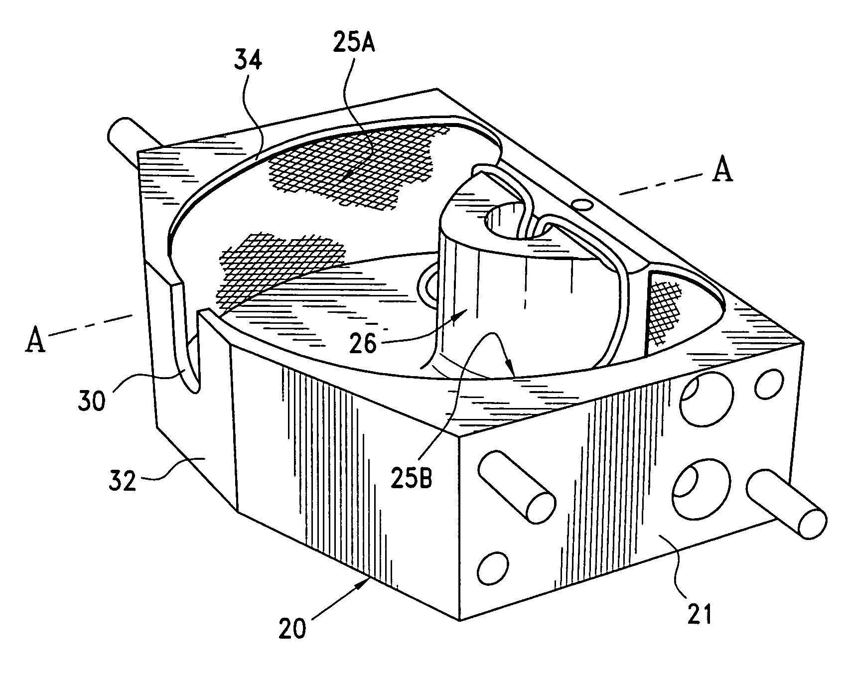
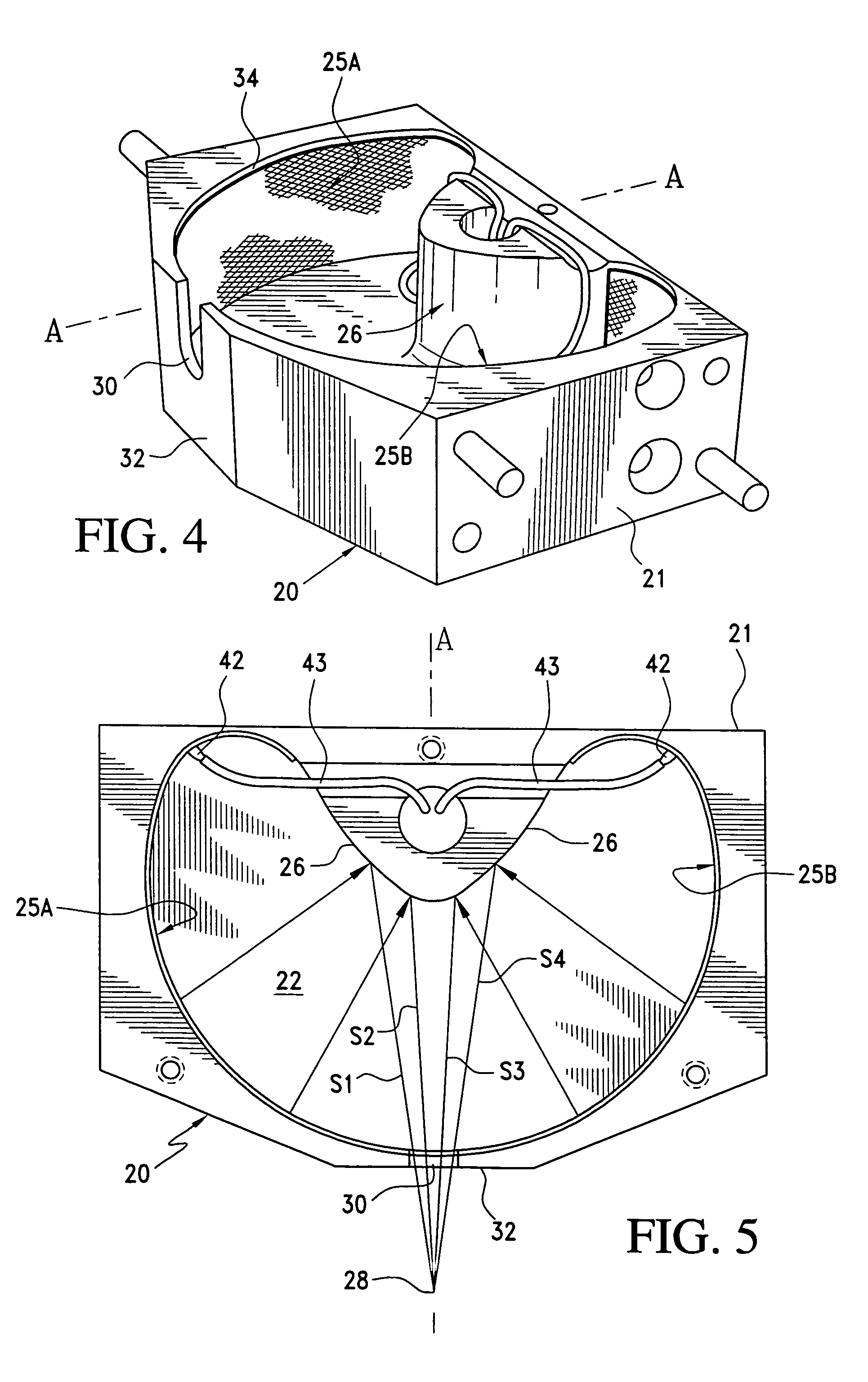
[0032] With specific reference to FIG. 4, the present invention is shown. In the embodiment, transducer 20 includes a housing 21 which is shown having a cover portion removed. The transducer housing includes an enclosed lower wall 22 which, with the upper removed cover, define a generally arcuate open area 24 which separate a pair of arcuate sonic radiating elements 25A and 25B from an opposing primary energy reflecting or reflector surface 26. Sonic energy radiated outwardly relative to the reflective surface 26 is focused at a point 28, see FIG. 5, exteriorly of the transducer after passing through an opening 30 in a front wall 32 of the transducer housing.

[0033] The housing 21 of the transducer 20 may be formed of a metallic or nonmetallic material. In the embodiment shown, a front arcuate inner wall 34 is molded or machined in order to provide support for the radiating elements which, in the embodiment, includes the two radiating elements 25A and 25B which are respectively provi...

second embodiment

[0042] With specific reference to FIG. 8, the invention is shown. In this embodiment, the transducer 50 includes a housing 51 which is designed to be closed at both the upper and lower portions, however, the upper cover is shown as being removed in the drawing figure. The housing defines an internal open area or cavity 53 which is defined by a first generally cylindrical radiating element 54 which opposes a primary first reflecting wall or surface 55 which is generally concave in configuration with respect to the first radiating wall. The radiating element or elements associated with the transducer are essentially the same as described with respect to the previous embodiment and will not be described in further detail with respect to the current embodiment. Thus, one or a plurality of radiating elements including an electrode, vibrating film and support mesh may be provided along the inner concave wall 52 of the present embodiment.

[0043] In the present embodiment, energy reflected f...


PUM


Abstract

Ultrasonic transducers which include at least one internally directed generally concavely configured sonic energy radiating element which directs sonic energy toward at least one arcuate energy reflecting surface which redirects and focuses the energy through an opening in a housing defining the transducer. The configuration of the at least one radiating element and the at least one energy reflecting surface are such that sound waves from substantially any point along the radiating element to the reflecting surface and to a focus exteriorly of the opening are substantially equal. The transducers function to focus energy either as transmitters or receivers.

Description

BACKGROUND OF THE INVENTION [0001] 1. Field of the Invention [0002] This invention is directed to transducer devices for focusing energy of sonic, audible and ultrasonic waves in either transmitting devices such as loudspeakers and ultrasonic transmitters and receiving devices such as microphones and ultrasonic receivers. More particularly, the present invention is directed to transducers designed to maximize a sound radiating or receiving surface for focusing energy either being radiated from, or being received relative to, the transducers. BRIEF DESCRIPTION OF THE RELATED ART [0003] A variety of sonic energy transmitting and receiving devices are known which utilize thin film radiating elements. Such devices use the thin film to convert electrical signals into vibrations within a transmitting media such as in air, for air-coupled devices, or in water or other liquids, for liquid-coupled devices. The films may include, but are not limited to, metalized plastic films such as used in...

Claims


Application Information

Patent Timeline
Patent Type & Authority Applications(United States)
IPC IPC(8): H04B1/02
CPCG10K11/28
Inventor NEESON, IAN ANDREWKNELLER, MIKHAIL
Owner PACKAGING TECH & INSPECTION LLC AKA PTI
Why Eureka
Try Eureka