Gas cylinder dispensing valve

a technology of gas cylinder and dispensing valve, which is applied in the direction of fluid pressure control, process and machine control, instruments, etc., can solve the problems of valve leakage between its filling and use, and achieve the effect of simple operation of the gas cylinder dispensing valv

Inactive Publication Date: 2006-03-23
PRAXAIR TECH INC +1
View PDF4 Cites 43 Cited by
  • Summary
  • Abstract
  • Description
  • Claims
  • Application Information

AI Technical Summary

Benefits of technology

[0007] A control knob is provided to rotate the rotating control shaft and a contact element is associated with the control knob so as to rotate therewith. The contact element is configured to impart motion to the isolation valve at the protruding portion and against the bias such that rotation of the control knob to and from an off position causes the isolation valve to move between the closed position and the open position and adjusts the flow control valve and therefore controls the flow of the gas.
[0008] Thus, in the present invention, the control knob is able to adjust both the flow of the gas to be dispensed and to activate the isolation valve. As such, the operation of a gas cylinder dispensing valve is simpler than prior art designs that utilize two knobs for such purposes. Additionally, the use of a biased isolation valve allows the entire dispensing valve to be constructed with less separate moving parts. Other advantages of the present invention will become apparent from the following discussion.

Problems solved by technology

The primary problem with the use of such dispensing valves is the tendency of the valve to leak between its filling and usage.
This is mostly due to temperature shrinkage of different materials utilized within the valves.

Method used


Image

  • Gas cylinder dispensing valve
  • Gas cylinder dispensing valve
  • Gas cylinder dispensing valve

Examples


Embodiment Construction

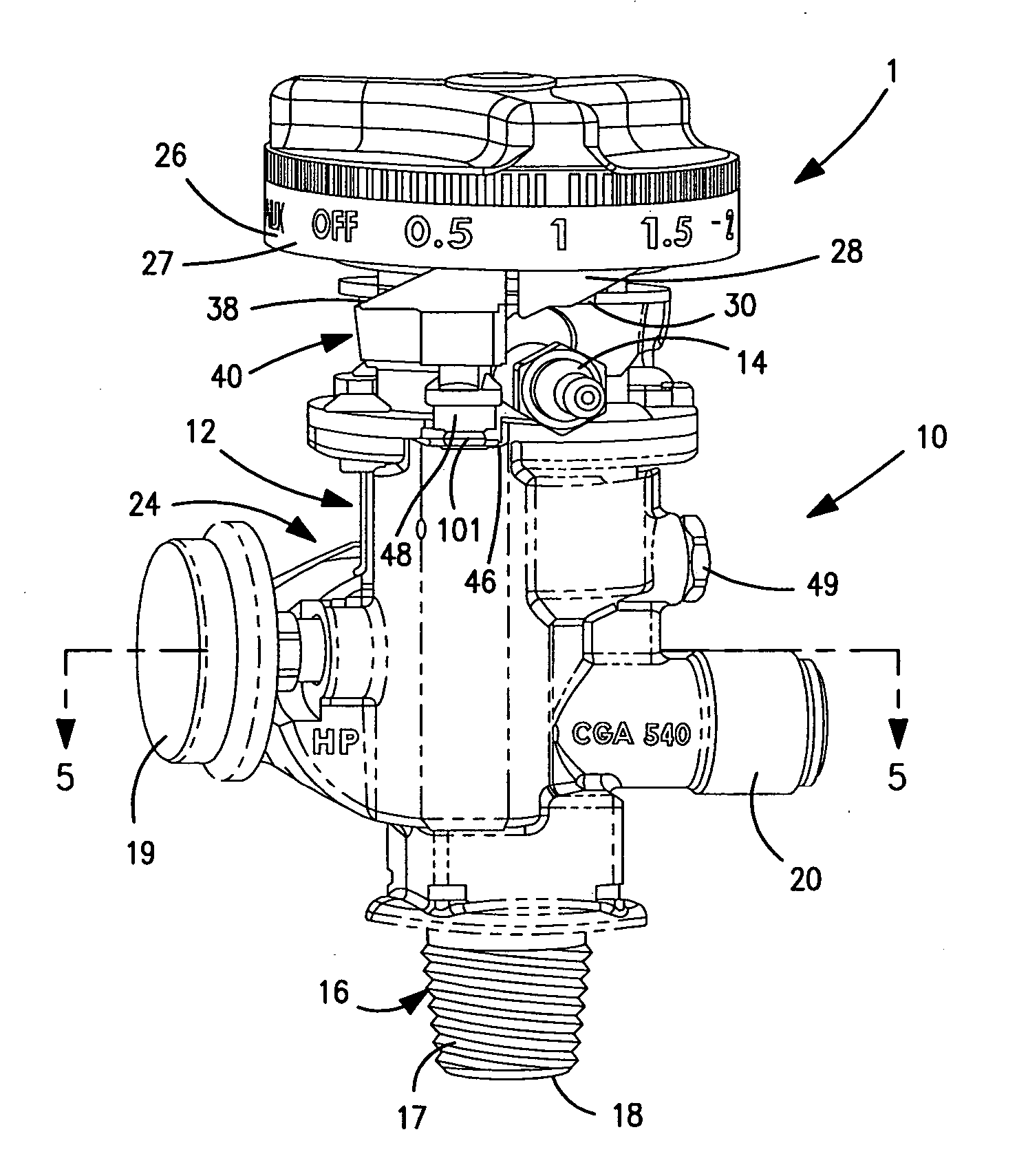
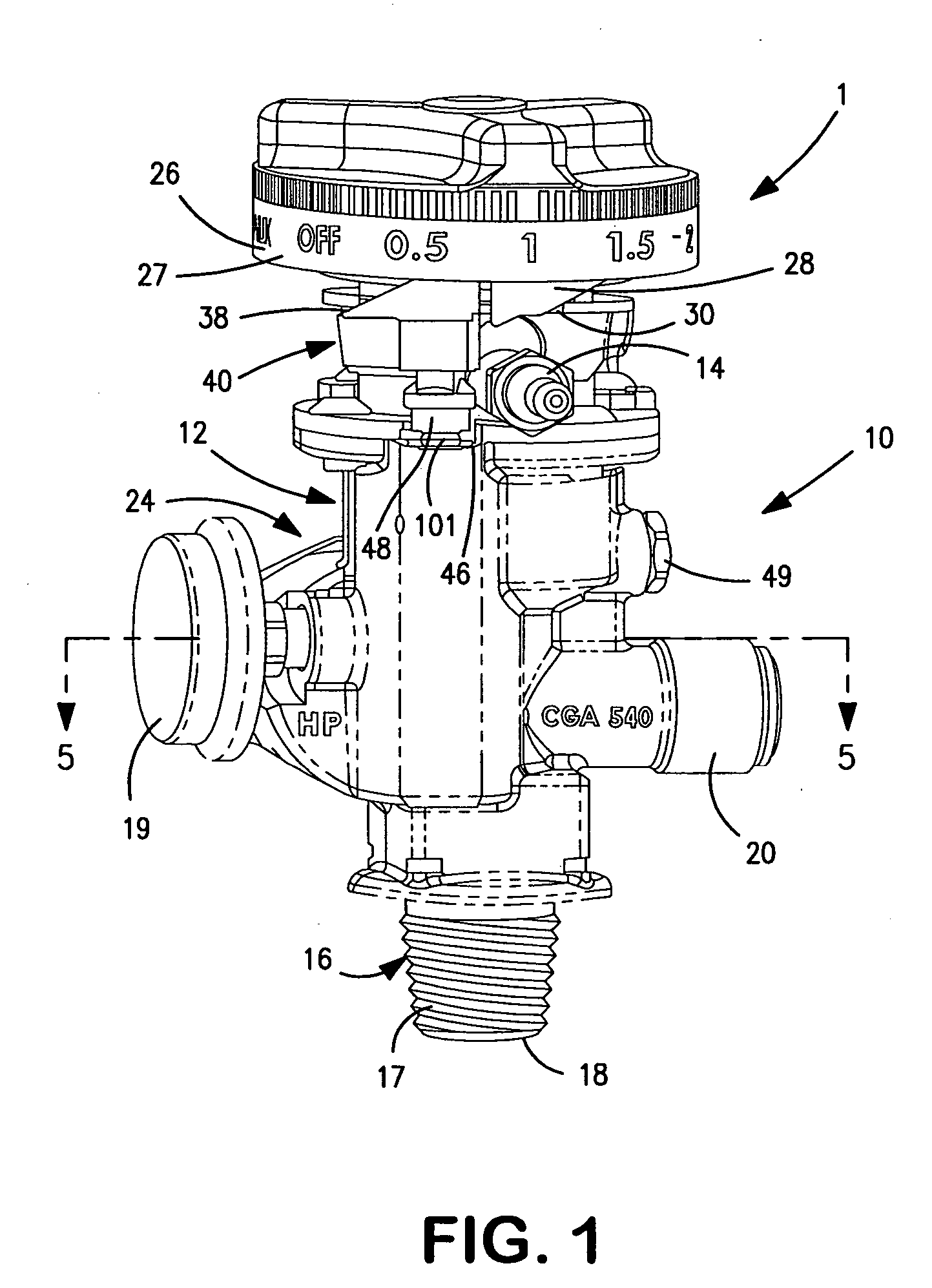
[0030] With reference to FIG. 1 a gas cylinder dispensing valve 1 in accordance with the present invention is illustrated. The specific embodiment illustrated is designed to dispense oxygen for therapeutic purposes. This being said, such specific embodiment is not to be taken as limiting in that the present invention is equally applicable to other gas dispensing applications that require the use of compressed gas cylinders and the dispensing of the gas at a regulated pressure and at regulated flow rates.

[0031] Gas cylinder dispensing valve 1 is provided with a body 10 that includes a top section 12 having a gas outlet 14 to discharge the gas to be dispensed. As illustrated, gas outlet 14 is in the form of a nipple-like fitting designed to couple with a hose for dispensing the oxygen for therapeutic purposes. Body 10 is also provided a lower section 16 that is configured to couple with an open head portion of a compressed gas cylinder, not illustrated, by way of threads 17.

[0032] W...


PUM


Abstract

A gas cylinder dispensing valve having an internal flow path provided with a pressure regulator. A biased isolation valve is provided within the flow path between the pressure regulator and a gas inlet of the valve and a flow control valve is provided within the flow path between the pressure regulator and a gas outlet to discharge the gas. Both isolation valve and the flow control valve can be manipulated by a single control knob which when set in an off position closes the isolation valve. The control knob can be rotated from the off position to select discrete, calibrated flow rates or an auxiliary position in which gas may be dispensed at a regulated pressure from an auxiliary outlet port.

Description

FIELD OF THE INVENTION [0001] The present invention relates to a gas dispensing valve for dispensing gas from a compressed gas cylinder. More particularly, the present invention relates to such a gas cylinder dispensing valve in which a flow control valve is provided to adjust the flow rate of the gas to be dispensed and an isolation valve is provided to cut off the flow of gas. More particularly, the present invention relates to such a gas cylinder dispensing valve in which a single control knob adjusts the flow control valve and activates the isolation valve. BACKGROUND OF THE INVENTION [0002] Industrial gases such as those obtained from the fractionation of air, can be delivered and utilized with the use of portable compressed gas cylinders. For instance, hospitals routinely use portable gas cylinders containing breathable compressed gases for patients during the course of their stay. The gas cylinder is normally connected to a pressure regulator to reduce the pressure of the gas...

Claims


Application Information

Patent Timeline
Patent Type & Authority Applications(United States)
IPC IPC(8): F16K21/00
CPCF16K1/305F16K1/306G05D7/0133F16K17/30F16K31/60F16K1/307Y10T137/87917
Inventor GAMARD, STEPHAN C.F.BIELEC, BRYAN R.EYTCHISON, GREGORY B.QUEST, JOEPOLAKOWSKI, ANTHONY R.SMALHEER, JEFFREY A.
Owner PRAXAIR TECH INC
Why Eureka
Try Eureka