Image compression/decompression system employing pixel thinning-out and interpolation scheme

a compression/decompression system and image compression technology, applied in the field of image compression/decompression system, can solve the problems of affecting image quality and affecting image quality, and achieve the effect of reducing data processing time and reducing data processing resources

Inactive Publication Date: 2006-05-11
RICOH KK
View PDF15 Cites 2 Cited by
  • Summary
  • Abstract
  • Description
  • Claims
  • Application Information

AI Technical Summary

Benefits of technology

[0009] An object of the present invention is to solve the above-mentioned problem, and, to provide an image compression / decompression schemes having a pixel thinning-out / interpolation schemes, by which, efficient image data compression / decompression can be attained by an effectively reduced data processing time, reduced data processing resources, but without remarkable apparent degradation in image quality during image data compression / decompression processing.
[0010] For this purpose, according to the present invention, as shown in FIG. 2, pixels to be thinned out are determined to be those arranged obliquely or in a staggering manner, not straightly vertically or horizontally. Thereby, it is possible to prevent a lot of thin lines, edge lines and so forth extending horizontally or vertically included in a natural image from being lost through image data compressing processing.

Problems solved by technology

Thereby, it is possible that, even when vertically extending thin lines included in a natural image are lost partially by the thinning-out processing, this may not result in remarkable apparent degradation of image quality.

Method used


Image

  • Image compression/decompression system employing pixel thinning-out and interpolation scheme
  • Image compression/decompression system employing pixel thinning-out and interpolation scheme
  • Image compression/decompression system employing pixel thinning-out and interpolation scheme

Examples


first embodiment

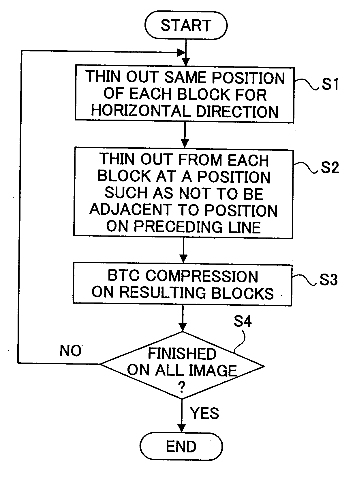
[0113]FIGS. 10 and 11 are flow charts showing flows of processing of the above-described image compressing / decompressing methods. That is, FIG. 10 is a flow chart illustrating an example of a flow of processing according to an image compression technology according to the present invention, and FIG. 11 is a flow chart illustrating an example of a flow of image decompression processing according to the present invention for decompressing image data compressed according to the processing illustrated in FIG. 10.

[0114] The flow of the image compression processing shown in FIG. 10 will now be described.

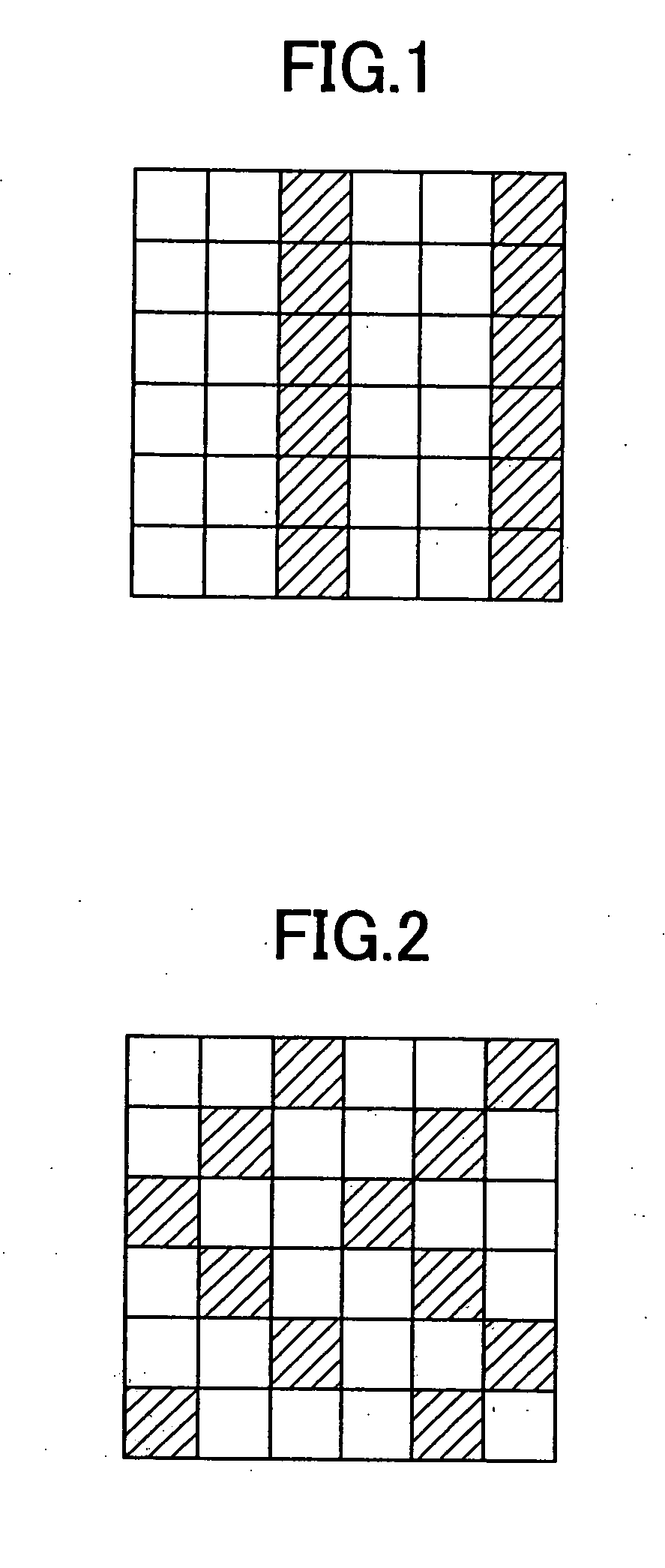
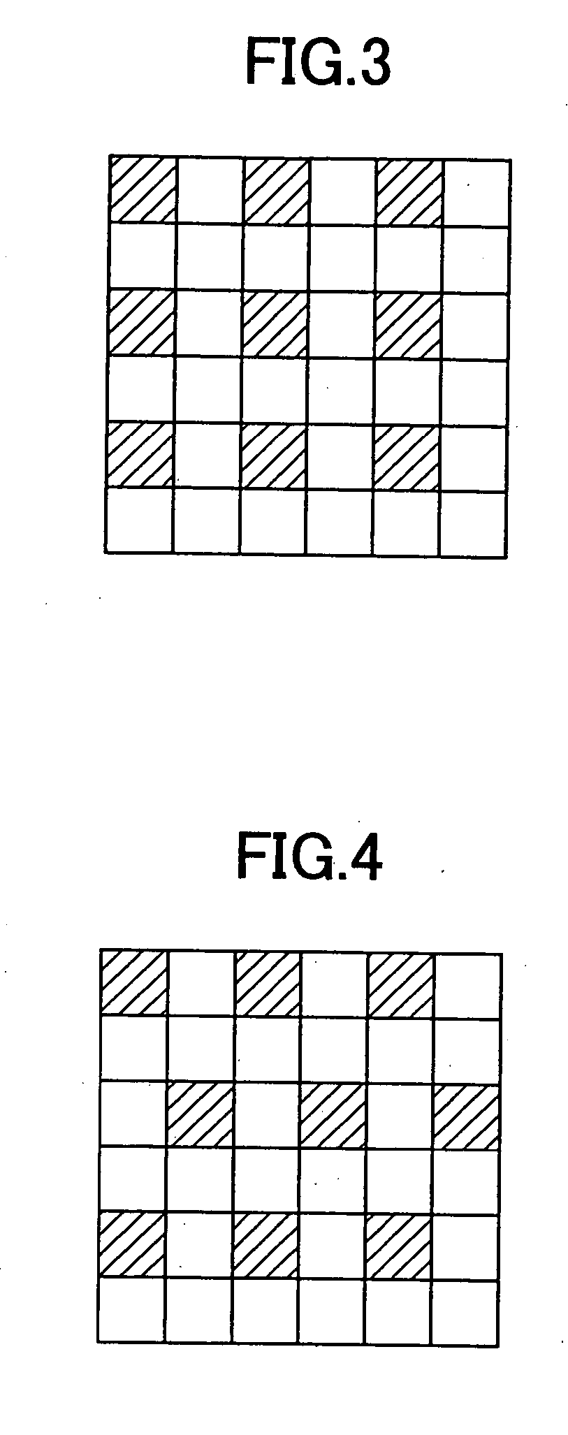
[0115] When compressing horizontally original image blocks each including 2×3 pixels which is a unit area to be compressed, the block of 2×1 pixels to be thinned out is located in the same position with respect to each original block (for example, the right end) throughout the same line (in a step S1). On the other hand, with respect to the vertical direction, the location of the thinned-...

second embodiment

[0124] With reference to FIG. 7, image compression scheme and interpolation scheme according to the present invention in case the number of pixels in a vertical direction of thinning-out / thinned-out block is equal to or more than three will now be described.

[0125] In FIG. 7, in case color image data is compressed, each of original image blocks from which thinning-out blocks are thinned out / removed includes 3×3 pixels. In the figure, 3×2 pixels shown as a white portion of each original image block are extracted as a compressed block after image compression, and 3×1 pixels shown as a hatched portion at the right or left end of each original image block are removed as a thinned-out block.

[0126] Specifically, during image data compression according to the second embodiment of the present invention illustrated by FIG. 7, on the horizontal direction, the position of the thinning-out / thinned-out block with respect to each original image block is the same for the same line. However, on the...

third embodiment

[0139] With reference to FIG. 8, image compression scheme and interpolation scheme according to the present invention in case the number of pixels of thinning-out / thinned-out block is half the number of the original image block will now be described.

[0140] In FIG. 8, in case color image data is compressed, each of original image blocks from which thinning-out blocks are thinned out includes 2×4 pixels. In the figure, 2×2 pixels shown as a white portion of each original image block are extracted as a compressed block after image compression, and 2×2 pixels shown as a hatched portion at the right or left end of each original image block are removed off as a thinned-out block.

[0141] Specifically, during image data compression according to the third embodiment of the present invention illustrated by FIG. 8, on the horizontal direction, the position of the thinning-out / thinned-out block with respect to each original image block is the same for the same line. However, on the vertical dir...


PUM


Abstract

An improved image thinning-out processing scheme includes processes of performing pixel thinning-out operation and compressing image data; and determining a position of pixel to be thinned out along a first direction depending on the position thereof along a second direction perpendicular to the first direction.

Description

BACKGROUND OF THE INVENTION [0001] 1. Field of the Invention [0002] The present invention generally relates to an image compression / decompression system, in particular, to an image compression / decompression system employing efficient pixel thinning-out and interpolation schemes. [0003] An image compression / decompression system according to the present invention may be applied widely to various image processing application programs, various device drivers (software) such as printer drivers, also, to various image processing apparatus / equipment processing color images. [0004] 2. Description of the Related Art [0005] With regard to image compression / decompression techniques, various schemes have been proposed. For example, Japanese laid-open patent application No. 7-221993 discloses a color image data thinning-out method, and a color image data compression method. In the methods, according to change rates in U data and V data representing color components, a size of pixel zone to be th...

Claims


Application Information

Patent Timeline
Patent Type & Authority Applications(United States)
IPC IPC(8): G06K9/36H04N1/41H04N7/26
CPCH04N19/90H04N19/91
Inventor YAMADA, MAIKO
Owner RICOH KK
Why Eureka
Try Eureka