Engine output control apparatus

a technology of engine output and control apparatus, which is applied in the direction of process and machine control, braking system, instruments, etc., can solve the problems of vehicle rapid acceleration and need for shift chang

Inactive Publication Date: 2006-05-25
MITSUBISHI FUSO TRUCK AND BUS CORPORATION
View PDF1 Cites 10 Cited by
  • Summary
  • Abstract
  • Description
  • Claims
  • Application Information

AI Technical Summary

Benefits of technology

[0011] The object of the present invention is to provide an apparatus for controlling an engine output under cooperation control which can prevent a stall or abrupt acceleration in a shift change.

Problems solved by technology

On the other hand, the shift change becomes necessary due to various causes involved.
This involves a problem that the vehicle is quickly accelerated.

Method used


Image

  • Engine output control apparatus
  • Engine output control apparatus
  • Engine output control apparatus

Examples


Embodiment Construction

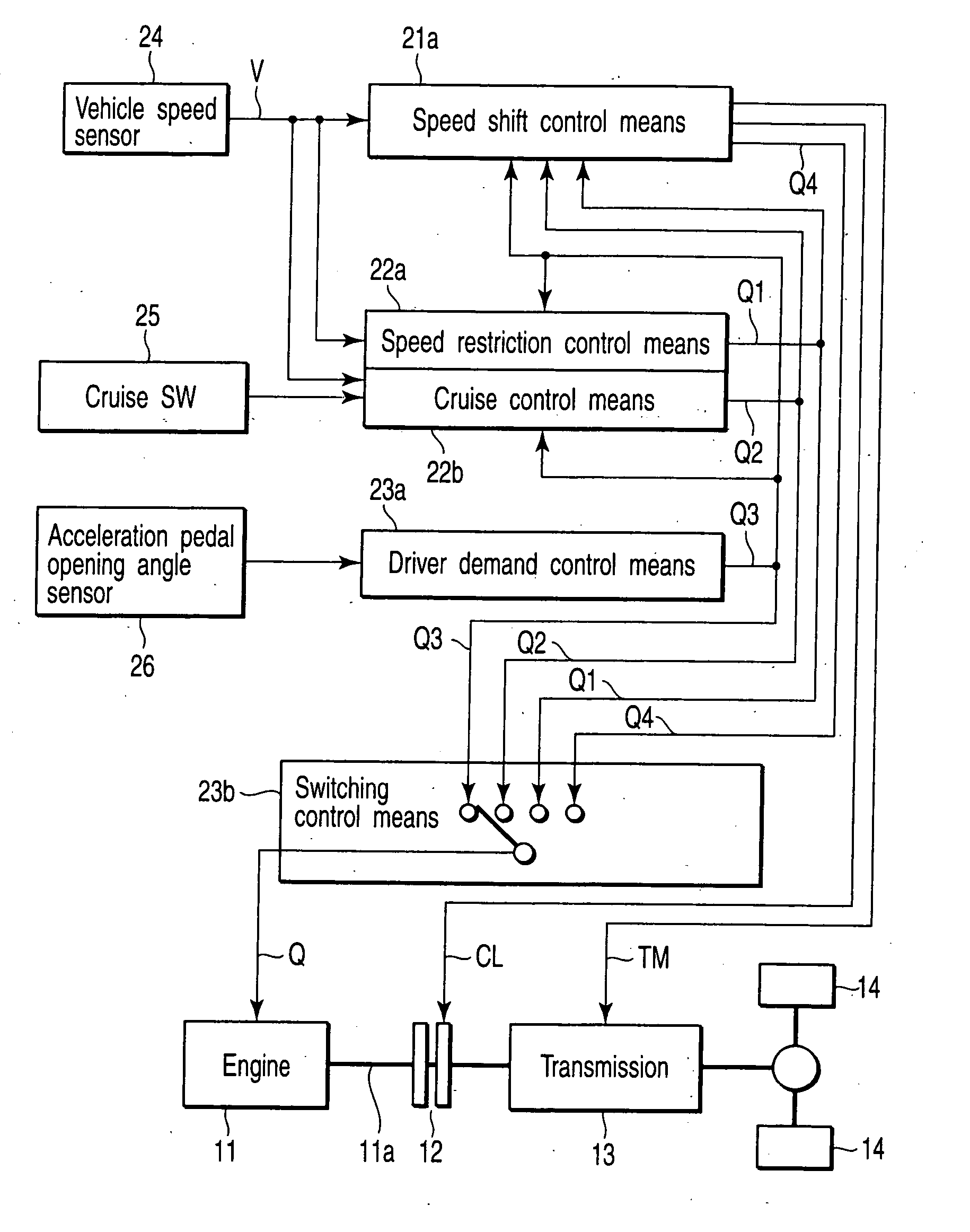
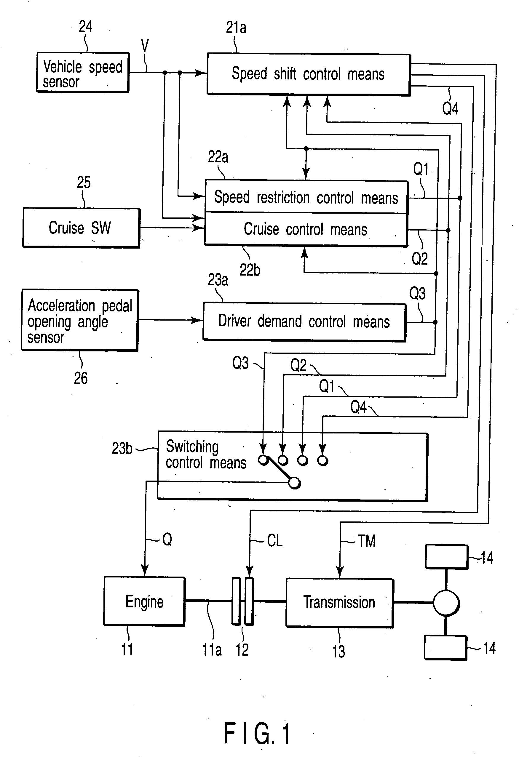
[0021] With reference to the drawing, an explanation will be made below about one embodiment of the present invention. FIG. 1 is a block diagram showing an apparatus for controlling a fuel injection amount under cooperation control. In the Figure, reference numeral 1 shows an engine and the rotation of an output shaft lla of the engine 11 is transmitted to drive shafts through a clutch 12 and transmission 13.

[0022] The control of the output of the engine 11 is done by controlling a fuel injection amount Q which is supplied to the engine 11. The fuel injection amount Q is calculated by respective means mounted on later-described speed shift control ECU (Electronic Control Unit) 21, MVCU (Multi Vehicle Control Unit) 22 and engine ECU 23.

[0023] Reference numeral 24 shows a vehicle speed sensor for detecting the vehicle speed. The vehicle speed V which is detected by the vehicle speed sensor 24 is input to vehicle speed control means 21a, speed restriction control means 22 and cruise ...


PUM


Abstract

An apparatus comprises a cruise control section to control an engine output according to an acceleration/deceleration demand set according to an acceleration/deceleration demand from a driver or a cruise control demand set to match an actual vehicle speed to a preset vehicle speed or to match a vehicle distance relative to a forward-going vehicle to a preset value, whichever demand is greater, a speed shift control section to shift gears and to control the engine output, and a switch control section to switch the cruise control section and speed shift control section according to their priority order. The speed shift control section, upon being switched by the switching control section to the cruise control section after the completion of the shift changing, returns the engine output back to that previous switching state based on the cruise control section.

Description

CROSS-REFERENCE TO RELATED APPLICATIONS [0001] This application is based upon and claims the benefit of priority from prior Japanese Patent Application No. 2004-340899, filed Nov. 25, 2004, the entire contents of which are incorporated herein by reference. BACKGROUND OF THE INVENTION [0002] 1. Field of the Invention [0003] The present invention relates to an engine output control apparatus and, in particular, an apparatus for controlling a fuel injection amount under cooperation control. [0004] 2. Description of the Related Art [0005] In general, an engine output control apparatus controls a fuel injection amount based on an acceleration pedal opening angle corresponding to a driver's demand output—hereinafter referred to normal control. [0006] Further, with a cruise SW ON, the target value of the engine output is set not according to the acceleration pedal opening angle but according to a cruise-set vehicle speed or an actual vehicle distance relative to a forward-going vehicle and...

Claims


Application Information

Patent Timeline
Patent Type & Authority Applications(United States)
IPC IPC(8): B60T8/32B60K31/00F02D29/00F02D29/02
CPCB60W10/06B60W10/11B60W30/143B60W30/16
Inventor HIGASHI, TOSHIHIKOKAYANO, MASAYUKIMATSUURA, SHOGO
Owner MITSUBISHI FUSO TRUCK AND BUS CORPORATION
Why Eureka
Try Eureka