Temporary surveillance system

a technology of surveillance system and surveillance camera, applied in the field of surveillance system, can solve the problems of virtually unguarded construction site, easy tampering or destruction of surveillance camera, and inadequate conventional surveillance system, and achieve the effect of high reliability of us

Inactive Publication Date: 2006-06-08
CAM GUARD SYST
View PDF37 Cites 8 Cited by
  • Summary
  • Abstract
  • Description
  • Claims
  • Application Information

AI Technical Summary

Benefits of technology

[0007] The present invention provides a surveillance system which is especially advantageous for temporary use where a conventional surveillance system would be undesirable, such as at a construction site, outdoor concert event, or political rally. The system is transportable to the site in separate portions and then assembled on the site. Once assembled, the system is effectively indestructible, tamper-proof and highly reliable to use. Advantageously, once the system is no longer needed, it can be disassembled and used again in another location.
[0008] Accordingly, a temporary surveillance system is provided by the present invention which overcomes the inadequacies of conventional systems. The system is easily assembled at an area to be surveyed. The system is highly versatile for accommodating a number of different applications for example, for daytime and / or evening monitoring of construction sites, outdoor concert events, political rallies, or any other location or event which could benefit from ongoing surveillance.
[0009] Importantly, the system is designed to be easily assembled at a site, and effectively tamper-proof once assembled.

Problems solved by technology

On a building construction site, for example a site where an apartment building is under construction, such conventional surveillance systems are less than adequate, as the apartment building itself may be the target of theft or vandalism.
The nature of the building under construction lends itself to being climbed by persons intent on vandalism, and the camera used for surveillance can be easily tampered with or destroyed, leaving the construction site virtually unguarded.
As can be appreciated, such a solution to vandalism problems is costly and may not be as reliable as an unmanned, mechanical surveillance system.

Method used


Image

  • Temporary surveillance system
  • Temporary surveillance system
  • Temporary surveillance system

Examples


Embodiment Construction

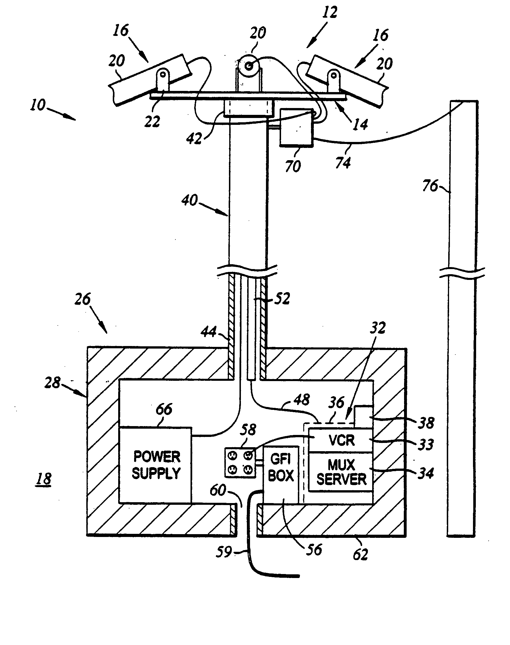
[0029] Turning now to FIG. 1, a surveillance system in accordance with the present invention is shown generally at 10. The system generally comprises a surveillance assembly 12, including a platform 14 adapted to support surveillance equipment 16 for providing observations of an area 18 in a vicinity of the surveillance system 10.

[0030] The surveillance equipment 16 may include any number and type of device 16 suitable for providing observations of objects. For the sake of simplicity, the surveillance devices 16 shown in FIG. 1 include a plurality of video cameras 20, though it is to be appreciated that the devices may alternatively or additionally include, for example, time lapse, digital, still photography cameras, and / or infrared sensors. The platform 14 may be sized and adapted to support any number of such cameras or sensors, for example between one and up to about 250 pieces of equipment. Furthermore, the surveillance equipment 16 may comprise a multiplexor, which may be a fo...


PUM


Abstract

A surveillance system is provided including a platform having a plurality and variety of cameras or sensors mounted thereto, and a base enclosure adapted to accommodate a power supply, a variety of electronics and other equipment for controlling and providing power to the surveillance equipment. The base is constructed to be tamper resistant and immovable by manual means. A substantially hollow support pole includes a lower portion detachably mounted to the base, and an upper portion mounted to the platform. Wires and cables for connecting the surveillance equipment with the electronics and power supply are run through the support pole. Power to the system may be supplied through existing power sources, for example a 120V power source.

Description

RELATED APPLICATIONS [0001] The present application is a continuation application of U.S. application Ser. No. 10 / 799,577, filed Mar. 11, 2004, which is a continuation application of U.S. application Ser. No. 10 / 127,017, filed Apr. 19, 2002, now U.S. Pat. No. 6,709,171, which is a continuation application of U.S. application Ser. No. 09 / 502,028, filed Feb. 10, 2000, now U.S. Pat. No. 6,375,370, the entireties of each of the above patent applications and patents are hereby incorporated by reference herein.BACKGROUND OF THE INVENTION [0002] 1. Field of the Invention [0003] The present invention relates to surveillance systems and more specifically relates to a temporary surveillance and security system. [0004] 2. Description of the Related Art [0005] Surveillance systems for monitoring remote installations are well known, and typically include on-site surveillance equipment, such as video cameras, microphones, infrared sensors and the like, positioned at various locations, to capture ...

Claims


Application Information

Patent Timeline
Patent Type & Authority Applications(United States)
IPC IPC(8): G03B17/00G08B13/196H04N7/18
CPCG03B17/00G08B13/19623G08B13/1963G08B13/19632G08B13/19634H04N7/181
Inventor WESSELINK, RICHARD H.WESSELINK, PAUL J.BROWN, STEPHEN FREDRICK
Owner CAM GUARD SYST
Why Eureka
Try Eureka