Image display device and image display method thereof

a technology of image display and display method, which is applied in the field of image display device, can solve the problems of reducing suppressing the deterioration of the picture quality of the motion picture, waste of consumed power of the backlight which is also on for a black display period, etc., and achieving the effect of suppressing the increase in consumed power and enhancing the picture quality of the dynami

Inactive Publication Date: 2006-08-03
KK TOSHIBA
View PDF3 Cites 31 Cited by
  • Summary
  • Abstract
  • Description
  • Claims
  • Application Information

AI Technical Summary

Benefits of technology

[0021] According to the invention, it is possible to enhance the picture quality of dynamic and still pictures displayed on the image display device while suppressing an increase in a consumed power.

Problems solved by technology

However, the liquid crystal display device and the organic EL display device have a problem in that a motion picture is blurred when it is displayed.
This problem is generated because a temporal characteristic of an image display method is varied between the liquid crystal display device or the organic EL display device and the CRT.
In the Patent Document 1, a screen of a liquid crystal is intentionally set to be “black” between the frames and an impulse type display such as a CRT is thus carried out falsely, resulting in suppression in deterioration in the picture quality of the motion picture.
However, the consumed power of a backlight which is also ON for a black display period is wasteful.
Moreover, there is a problem in that a flicker is caused by the impulse type display in a still picture.
For this reason, it is impossible to obtain a sufficient power consuming effect.
In that case, however, the picture quality of the motion picture is deteriorated.

Method used


Image

  • Image display device and image display method thereof
  • Image display device and image display method thereof
  • Image display device and image display method thereof

Examples


first embodiment

[0040] A liquid crystal display device 10 according to a first embodiment of the invention will be described with reference to FIGS. 1 to 7.

(1) Structure of Liquid Crystal Display Device 10

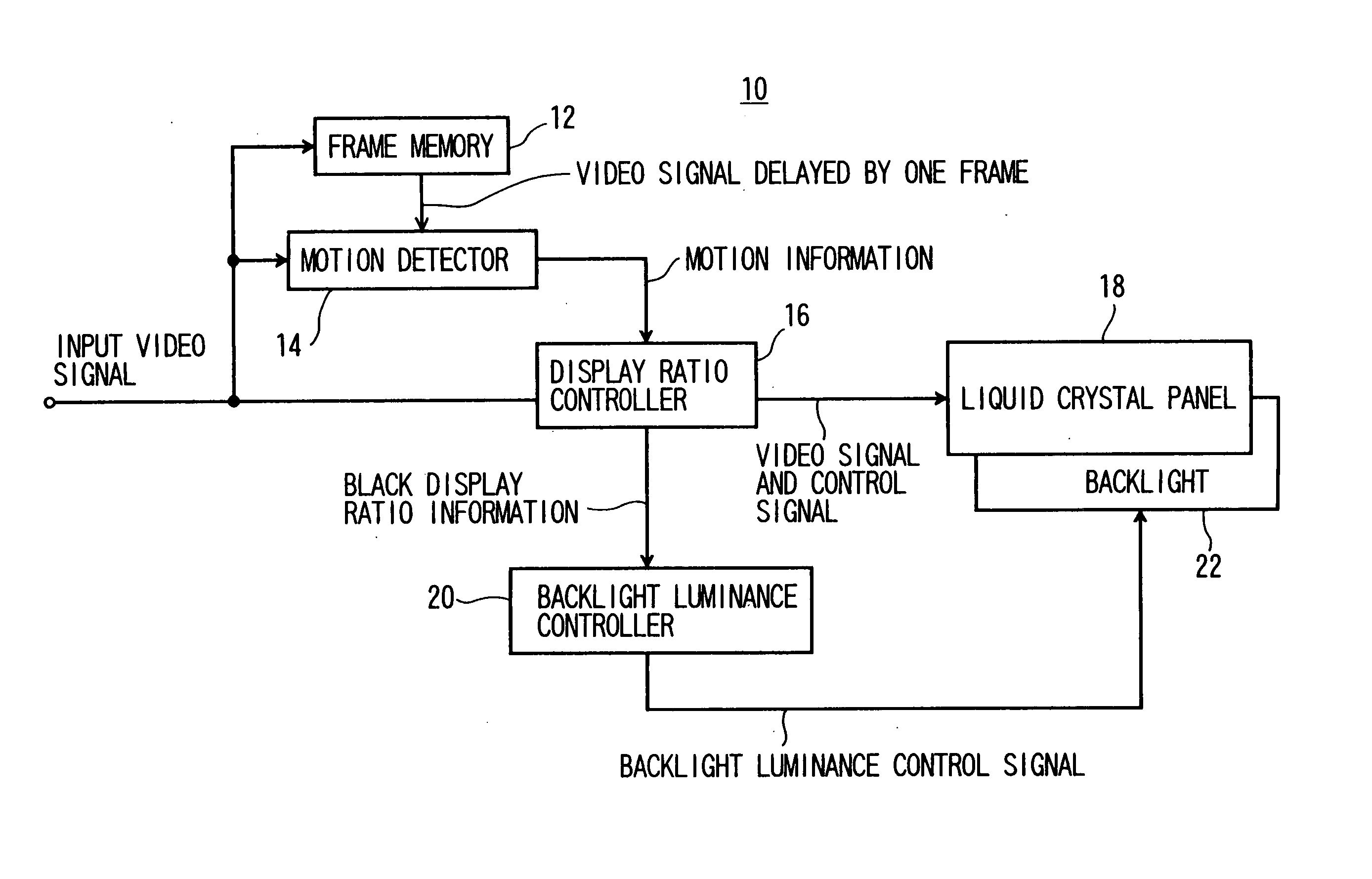
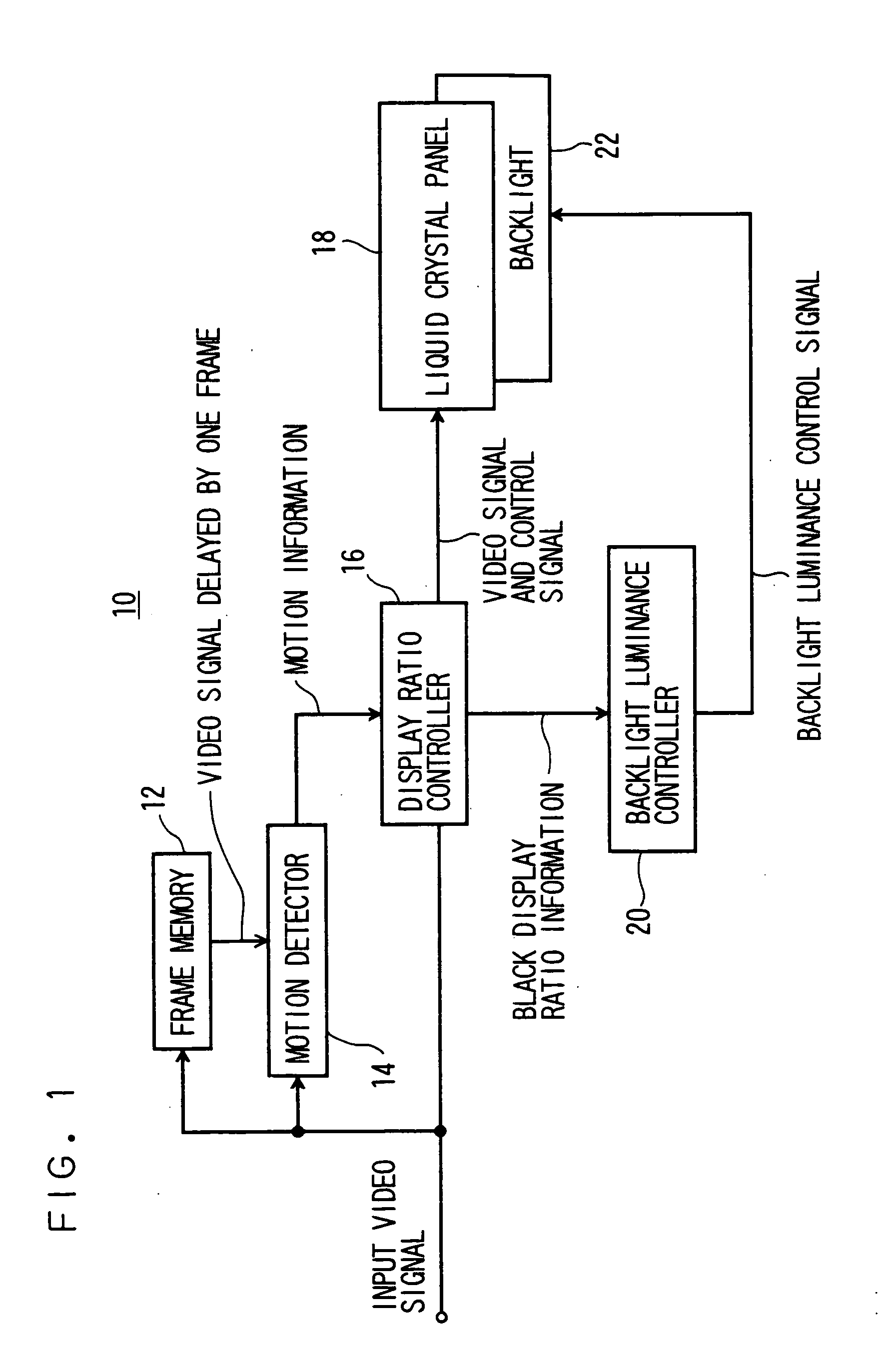
[0041]FIG. 1 shows a structure of the liquid crystal display device 10 according to the embodiment.

[0042] An input image signal is input to a frame memory 12, a motion detector 14 and a display ratio controller 16.

[0043] The frame memory 12 holds an input image signal for one frame period and outputs as an image signal delayed by one frame to the motion detector 14. The “one frame” indicates one image to be displayed on the liquid crystal display device 10 and it is assumed that one field which is generally referred in an interlace image signal and the one frame are indicated to, each other.

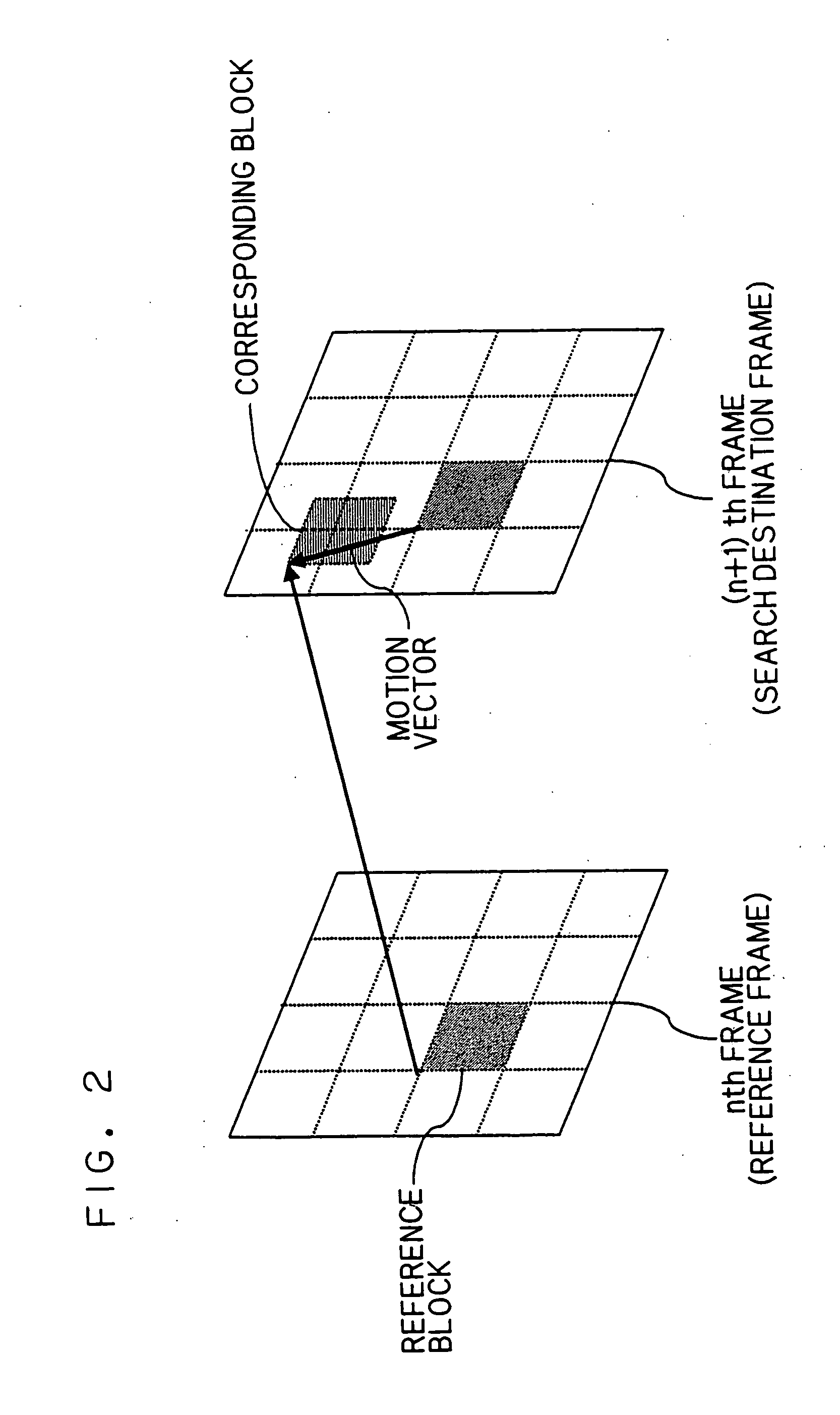
[0044] The motion detector 14 uses an input image signal and an image signal delayed by one frame period through the frame memory 12, thereby detecting a motion between two temporal adjacent frames and out...

second embodiment

[0122] A liquid crystal display device 10 according to a second embodiment of the invention will be described with reference to FIG. 8.

[0123]FIG. 8 shows a structure of the liquid crystal display device 10 according to the embodiment.

[0124] The liquid crystal display device 10 according to the second embodiment has a basic structure which is the same as that in the first embodiment, and an input image is a compressed image including motion vector information and the liquid crystal display device 10 includes a decoder 24 for the compressed image and has such a structure as to output the motion vector information obtained in a decoding process to a motion detector 14.

[0125] The compressed input image including the motion vector information is input to the decoder 24. The compressed image including the motion vector information is MPEG2, for example. An image used in a broadcast at present is changed into an image compressed by the MPEG2, and furthermore, most of images stored in a ...

third embodiment

[0128] A liquid crystal display device 10 according to a third embodiment of the invention will be described with reference to FIGS. 9 and 10.

(1) Structure of Liquid Crystal Display Device 10

[0129]FIG. 9 shows a structure of the liquid crystal display device 10 according to the third embodiment of the invention.

[0130] The liquid crystal display device 10 according to the third embodiment has a basic structure which is the same as that in the second embodiment and in which a one-dimensional image obtained by adding an input image in horizontal and vertical directions is used to detect a motion of the input image.

[0131] The input image is input to a one-dimensional image generator 26 and is converted from two-dimensional image data into one-dimensional image data. The one-dimensional image is input to a motion detector 14 together with a one-dimensional image delayed by one frame period through a memory 28 and motion information is generated in the same manner as in the first embo...


PUM


Abstract

An image display device comprising: a display 18 to display an input image and a black image within one frame period; a motion detector 14 to detect a motion information from the input image; a display ratio controller 16 to set a black display time ratio as a ratio of a black period to said one frame period based on the motion information, the black period being a period for displaying the black image within said one frame period; and a display luminance controller 30 to suppress, within a predetermined range, a luminance fluctuation caused by a change in the black display time ratio, the luminance fluctuation corresponding to a fluctuation of a total luminance for said one frame period.

Description

CROSS-REFERENCE TO RELATED APPLICATIONS [0001] This application is based upon and claims the benefit of priority from the prior Japanese Patent Application No. 2005-1887, filed on Jan. 6, 2005; the entire contents of which are incorporated herein by reference. TECHNICAL FIELD [0002] The present invention relates to an image display device capable of enhancing picture quality of a motion picture and a still picture while suppressing an increase in a consumed power. BACKGROUND OF THE INVENTION [0003] In recent years, a performance of a thin image display device such as a liquid crystal display device or an organic EL (electroluminescence) display device has been enhanced, and also has started to spread in the television field in which a cathode ray tube (hereinafter referred to as a CRT) is conventionally a mainstream. [0004] However, the liquid crystal display device and the organic EL display device have a problem in that a motion picture is blurred when it is displayed. This proble...

Claims


Application Information

Patent Timeline
Patent Type & Authority Applications(United States)
IPC IPC(8): H04N5/21H04N9/455H04N9/44H04N9/45H04N5/04
CPCG09G3/3225G09G3/3406G09G3/342G09G3/3648G09G2300/0842G09G2310/024G09G2310/08G09G2320/0261G09G2320/064G09G2320/10G09G2360/145H04N5/145G01R1/06716G01R1/06755G01R1/073
Inventor BABA, MASAHIROITO, GOMISHIMA, NAO
Owner KK TOSHIBA
Why Eureka
Try Eureka