
Nailing machine with a safety mechanism
a safety mechanism and nailing machine technology, applied in the field of nailing machines, can solve the problem of not yielding a safety concern for the nailing action, and achieve the effect of a higher degree of safety
- Summary
- Abstract
- Description
- Claims
- Application Information
AI Technical Summary
Benefits of technology
Problems solved by technology
Method used
Image

Examples
Embodiment Construction
[0021] The features and the advantages of the present invention will be more readily understood upon a thoughtful deliberation of the following detailed description of a preferred embodiment of the present invention with reference to the accompanying drawings.
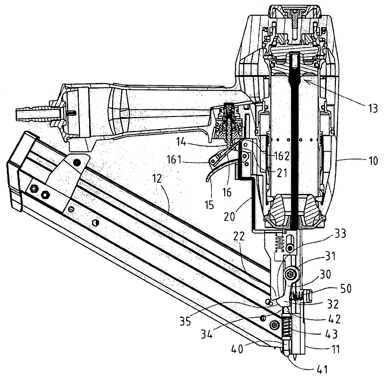
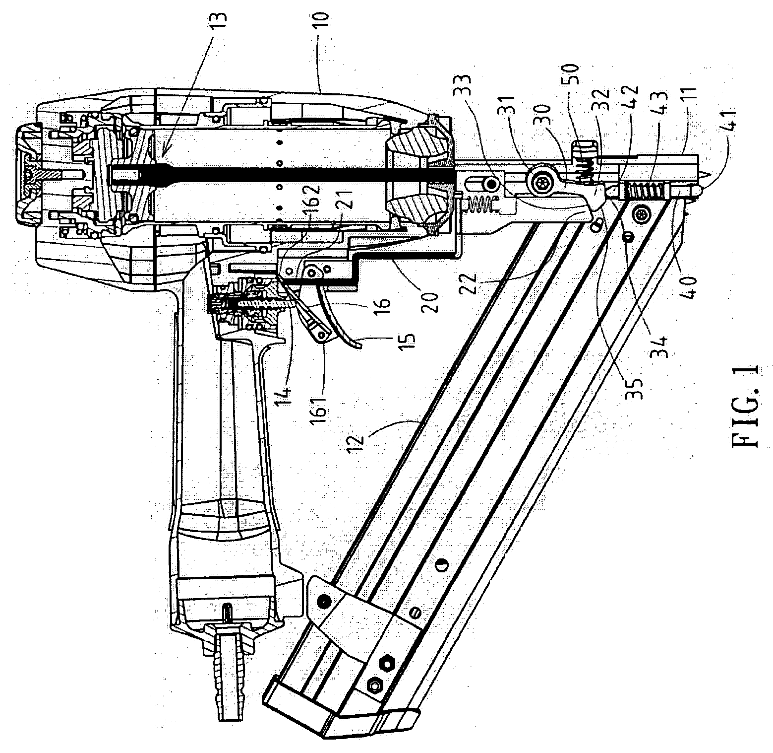
[0022] As shown in FIGS. 1-4, a nailing machine with safety mechanism embodied in the present invention comprises:
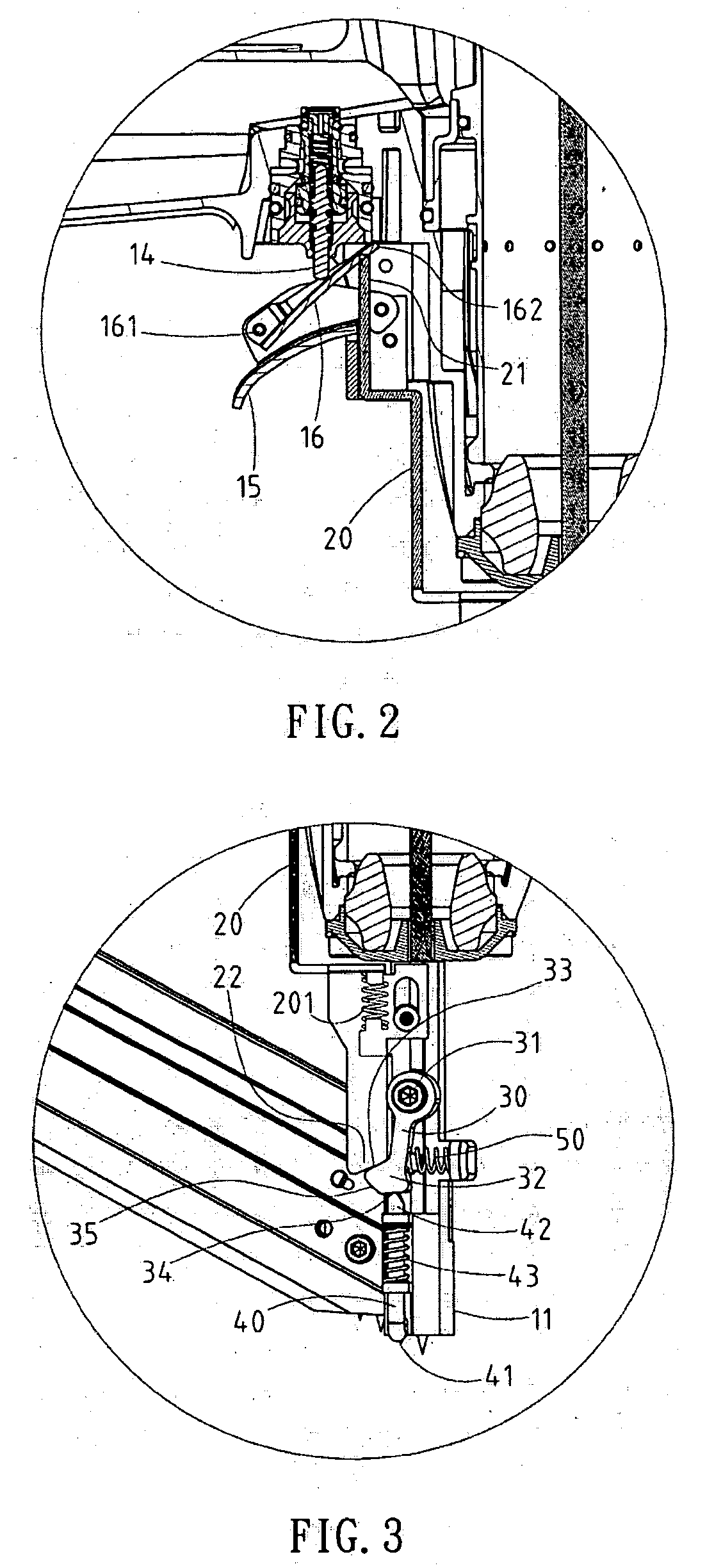
[0023] a mainframe 10, a nailing part 11, a cartridge 12, a drive part 13, a trigger switch 14, a fastener 15, a trigger 16 and a safety mechanism. The trigger 16 is located between the fastener 15 and trigger switch 14, where it is mounted onto inner side of a movable end of fastener 15 via a support 161 (a stud shaft in this embodiment). And, the inner side of movable end 162 of trigger 16 is linked to the trigger switch 14.
[0024] The safety mechanism, located between the trigger 16 and nailing part 11, comprises an adjustable shelf 20, which shifts recurrently along a straight track. The inner side 21 of adjus...
PUM
| Property | Measurement | Unit |
|---|---|---|
| obtuse angle | aaaaa | aaaaa |
| movement | aaaaa | aaaaa |
| flexible | aaaaa | aaaaa |
Abstract
Description
Claims
Application Information