Triggered data generator

a data generator and trigger technology, applied in the field of data generators, can solve the problems of inapplicability of the method using the dll, circuit cannot provide fast response, and the reading speed of the memory is not sufficient for the higher speed data pattern signal, so as to reduce uncertainty and shorten delay

Active Publication Date: 2006-09-14
TEKTRONIX INC
View PDF8 Cites 6 Cited by
  • Summary
  • Abstract
  • Description
  • Claims
  • Application Information

AI Technical Summary

Benefits of technology

[0011] The present invention reduces uncertainty to start of the serial data output from arrival of a trigger signal by shift operation of parallel data. Therefore serial data derived from the shifted parallel data by parallel to serial conversion, are provided with shorter delay from the arrival of the trigger signal than before.

Problems solved by technology

However, the reading speed from the memory is not sufficient for higher speed data pattern signals.
However, the circuit cannot provide fast response because it makes the VCO oscillate according to the trigger signal.
But the triggered clock CLK and divided clock are not continuous in the example of FIG. 1 since they are gated according to the trigger signal so that the method using the DLL is not applicable.

Method used


Image

  • Triggered data generator
  • Triggered data generator
  • Triggered data generator

Examples


Embodiment Construction

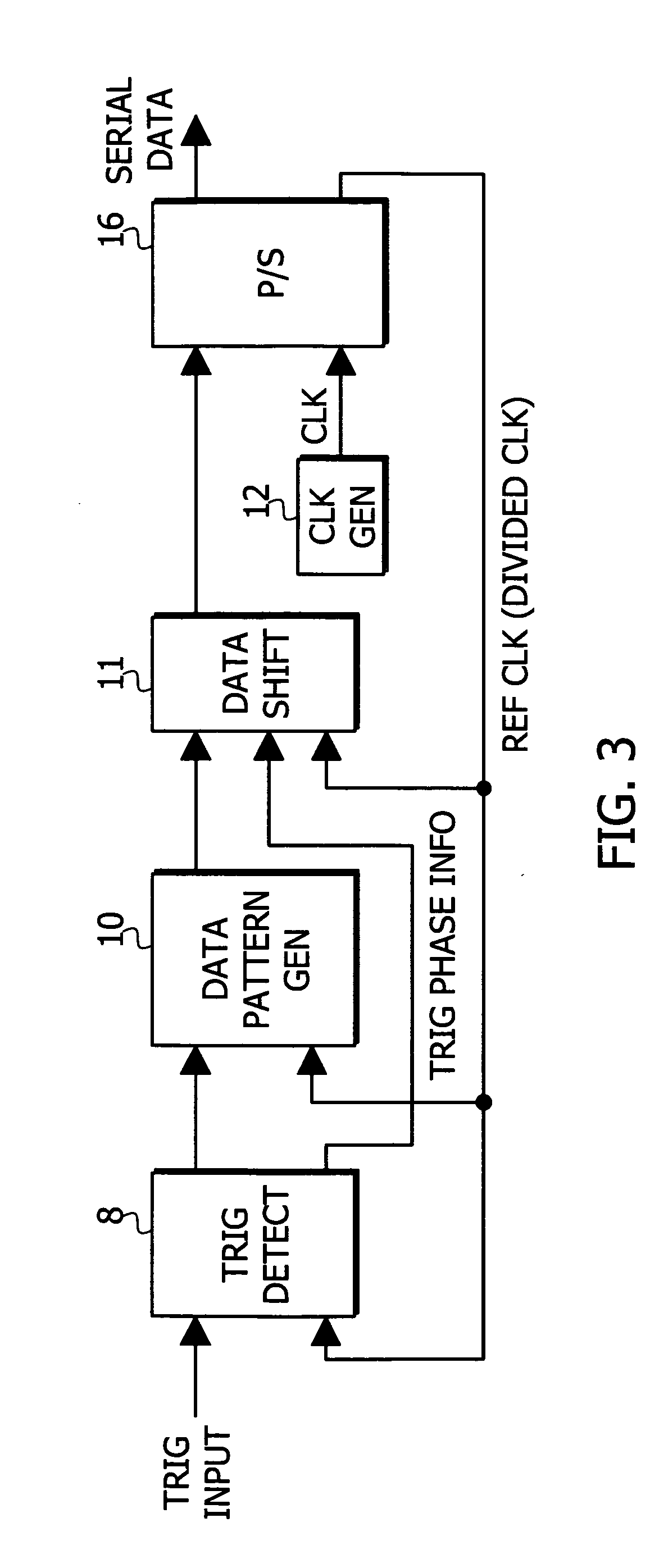
[0018] Referring to FIG. 3, there is shown a block diagran of a triggered data generator according to the present invention. A parallel to serial converter 16 provides serial data according to a clock (CLK) from a clock generator 12. The parallel to serial converter 16 also provides a divided clock output by dividing the clock CLK by the bit number of the parallel data. For example, if the parallel data has four bits, then the clock (CLK) from the clock generator 12 is divided by four. The divided clock will herein after be referred to as the reference clock. In the following descriptions, corresponding blocks in different Figs. are indicated by the same numbers.

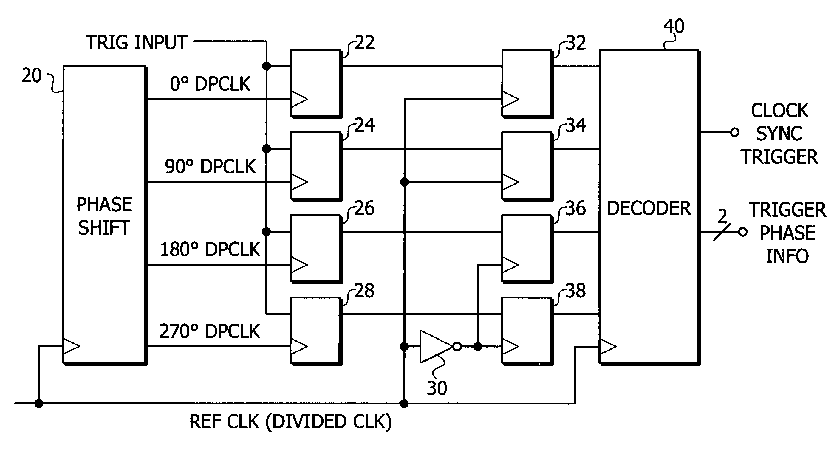
[0019] A trigger detector 8 receives a trigger signal and detects the phase of a trigger edge relative to the reference clock to provide trigger phase information and a signal indicating whether a trigger is effective or not. A data pattern generation circuit 10 receives the signal indicating whether the trigger is effectiv...


PUM


Abstract

A triggered data generator reduces timing jitter at the start of serial data output from arrival of a trigger signal. A trigger detecting circuit 8 produces trigger phase information indicating the phase relationship between the trigger signal and a reference clock. A data pattern generating circuit 10 generates parallel data bits according to the reference clock in response to the trigger signal. A data shifting circuit 11 rearranges the parallel data bits in a predetermined order to produce shifted parallel data bits in which data bit order is shifted relative to the reference clock as a function of the trigger phase information. A parallel to serial converter 16 converts the shifted parallel data bits into serial data bits.

Description

BACKGROUND OF THE INVENTION [0001] The present invention relates generally to data generators and more specifically to a fast data generator that starts data generation in response to a trigger signal. [0002] Data generators store data patterns in memory and read the data patterns out as parallel data. The parallel data is then processed in a parallel state. However, the reading speed from the memory is not sufficient for higher speed data pattern signals. Therefore, the need for faster data patterns has resulted in the parallel data being read out of memory as parallel data and then converted into serial data to accelerate the data speed. The data generator usually starts data generation according to a trigger signal. The below described data generators fall into this category. [0003]FIG. 1 is a block diagram of a conventional data generator. A clock generator 12 provides continuous clock CLK to a clock gate 14. The clock gate 14 passes the clock CLK according to a trigger signal. ...

Claims


Application Information

Patent Timeline
Patent Type & Authority Applications(United States)
IPC IPC(8): H03M9/00
CPCG06F1/025H03M9/00
Inventor FUJISAWA, YASUMASA
Owner TEKTRONIX INC
Why Eureka
Try Eureka