Display apparatus and display method

Active Publication Date: 2006-09-28
SATURN LICENSING LLC
View PDF55 Cites 120 Cited by
  • Summary
  • Abstract
  • Description
  • Claims
  • Application Information

AI Technical Summary

Benefits of technology

[0019] Accordingly, the emission luminance of a light source corresponding to one of the regions is computed while taking into account an effect on the region of the other light sources not corresponding to the region, and the aperture ratio of each pixel is controlled on the basis of the computed emission luminance. As a result, the emission luminance of the light sources is efficiently controlled and the power consumption is reduced while providing emission luminance required for every area of the display screen. Thus, the quality of an image can be increased.
[0020] As described above, a display method for use in a display apparatus is provided. The display apparatus includes a display unit having a display screen divided into a plurality of regions and being controlled using an aperture ratio on a pixel-by-pixel basis, and a backlight for illuminating the back surface of the display unit. The backlight includes a plurality of sets of light sources, each set being disposed so as to correspond

Problems solved by technology

Thus, the original image could not be faithfully played back.
Consequently, the portion e having a high disp

Method used


Image

  • Display apparatus and display method
  • Display apparatus and display method
  • Display apparatus and display method

Examples


Example

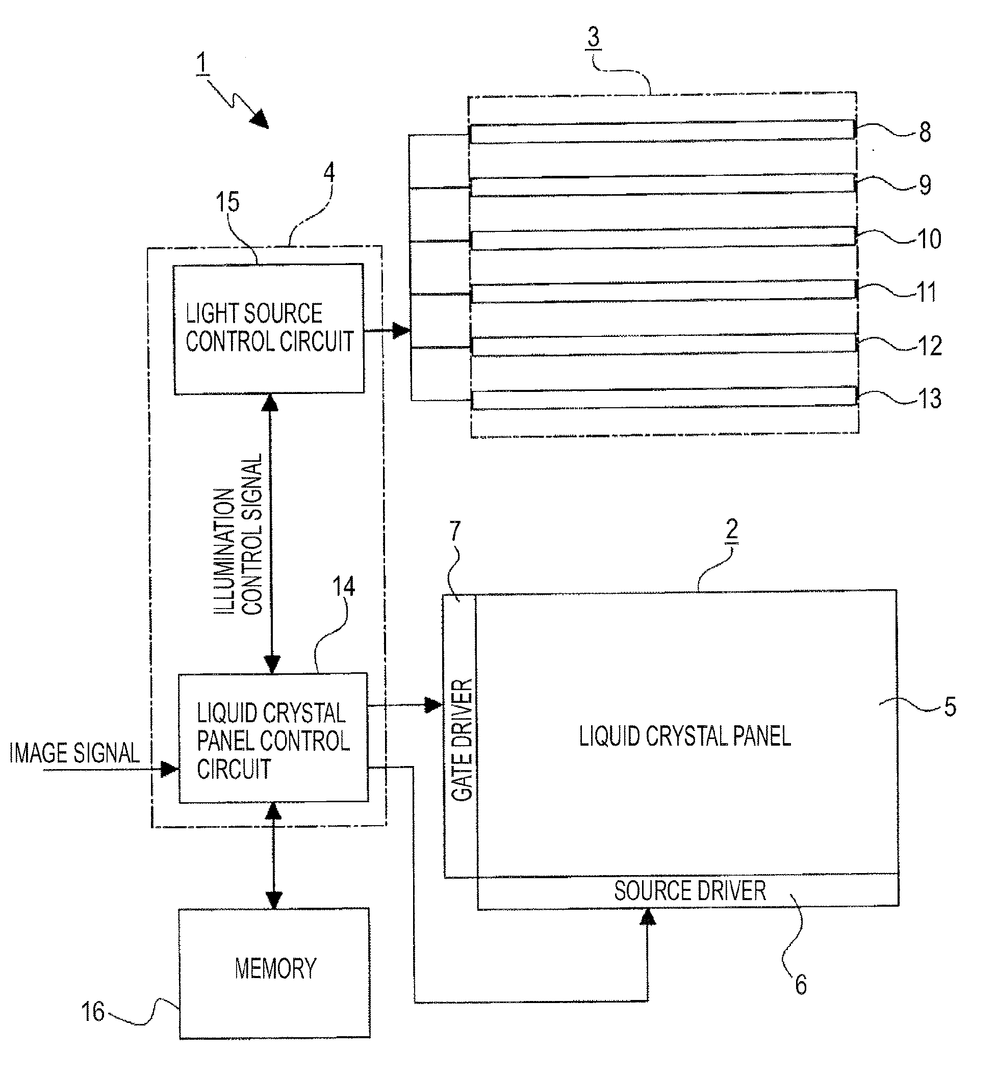
[0040] Exemplary embodiments of the present invention are now herein described with reference to FIGS. 1 to 17.

[0041] In the following exemplary embodiments, a display apparatus of the exemplary embodiments is applied to a liquid crystal display device and a display method of the exemplary embodiments is applied to a method for displaying an image on the liquid crystal display device.

[0042] However, it should be appreciated that the present invention is not limited in this respect. The present invention can be applied to all the display apparatuses and all the display methods for displaying an image on the display apparatus in which a backlight is disposed on the back surface of a display unit of the display apparatus and an image is displayed by controlling the aperture ratio of a pixel of the display unit.

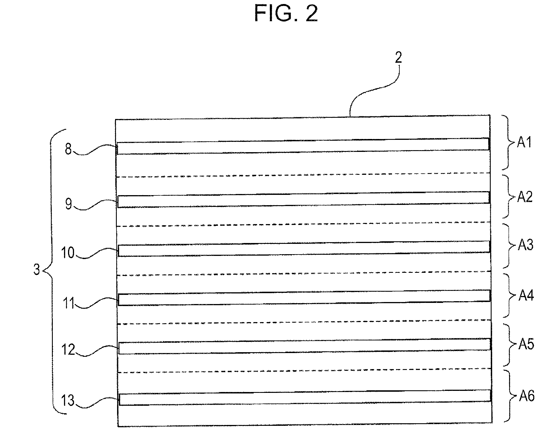
[0043] As shown in FIG. 1, a liquid crystal display device 1 includes a display unit 2 for displaying an image, a backlight 3 disposed on the back surface of the display unit ...


PUM


Abstract

A display apparatus includes a display unit having a display screen divided into a plurality of regions and controlled using an aperture ratio on a pixel-by-pixel basis, a backlight including a plurality of sets of light sources, each set being disposed so as to correspond to one of the regions, and a control unit for detecting display luminance in each region, computing the emission luminance of each light source on the basis of the detected display luminance while taking into account an effect on the region of the other light sources not corresponding to the region, and computing a correction value for each pixel on the basis of a shift amount between the set emission luminance and an optimal display luminance for one of the regions, and delivering a display driving signal generated on the basis of the correction value to each pixel so as to control the aperture ratio.

Description

CROSS REFERENCES TO RELATED APPLICATIONS [0001] The present invention contains subject matter related to Japanese Patent Application JP 2005-087102, JP 2005-182365, and JP 2005-331981 filed in the Japanese Patent Office on Mar. 24, 2005, Jun. 22, 2005, and Nov. 16, 2005, the entire contents of which are incorporated herein by reference. BACKGROUND OF THE INVENTION [0002] 1. Field of the Invention [0003] The present invention relates to a display apparatus and a display method suitable for use in, for example, a liquid crystal display device. [0004] 2. Description of the Related Art [0005] In display apparatuses, for example, liquid crystal display devices, since pixels of a liquid crystal panel do not emit light by themselves, a backlight is disposed on the back surface of the liquid crystal panel to illuminate the back surface of the liquid crystal panel. Thus, an image can be displayed. [0006] In known liquid crystal display devices, the backlight illuminates the entire display sc...

Claims


Application Information

Patent Timeline
IPC IPC(8): G09G3/36
CPCG09G3/342G09G3/3426G09G3/3648G09G2320/0233G09G2320/0285G09G2320/0646G09G2320/066G09G2330/021G09G2360/16G09G3/36G02F1/133G09G3/20
Inventor KIMURA, KAZUTOMASUDA, SHOZOHAYASHI, MASATAKE
Owner SATURN LICENSING LLC
Why Eureka
Try Eureka