Image display apparatus

a technology of image display and display screen, which is applied in the direction of optics, electrical equipment, instruments, etc., can solve the problems of limited observable range (a viewing zone) and the inability to produce a gap g smaller than the thickness of glass

Inactive Publication Date: 2006-09-28
KK TOSHIBA
View PDF11 Cites 29 Cited by
  • Summary
  • Abstract
  • Description
  • Claims
  • Application Information

AI Technical Summary

Benefits of technology

[0019] The present invention has been made in view of these circumstances, and an object thereof is to provide an image display apparatus where all pixel infor

Problems solved by technology

In case of a three-dimensional image display apparatus of an autostereoscopic system, a three-dimensional image can be viewed without using glasses, but an observable range (a viewing zone) is limited.
Further, a light ray group incident on a viewing position between two viewers spaced from each other within a viewing zone expanded for containing the two viewers does not contribute to a stereoscopic viewing of the viewers.
However, for example, when a liquid crystal display (LCD) is used as a two-dimensional image display apparatus, since a pixel portion of the liquid cr

Method used


Image

  • Image display apparatus
  • Image display apparatus
  • Image display apparatus

Examples


example 2

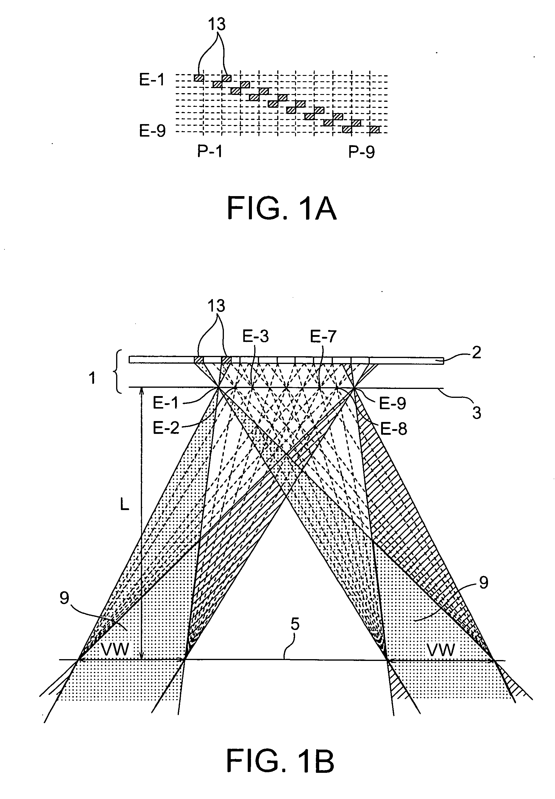
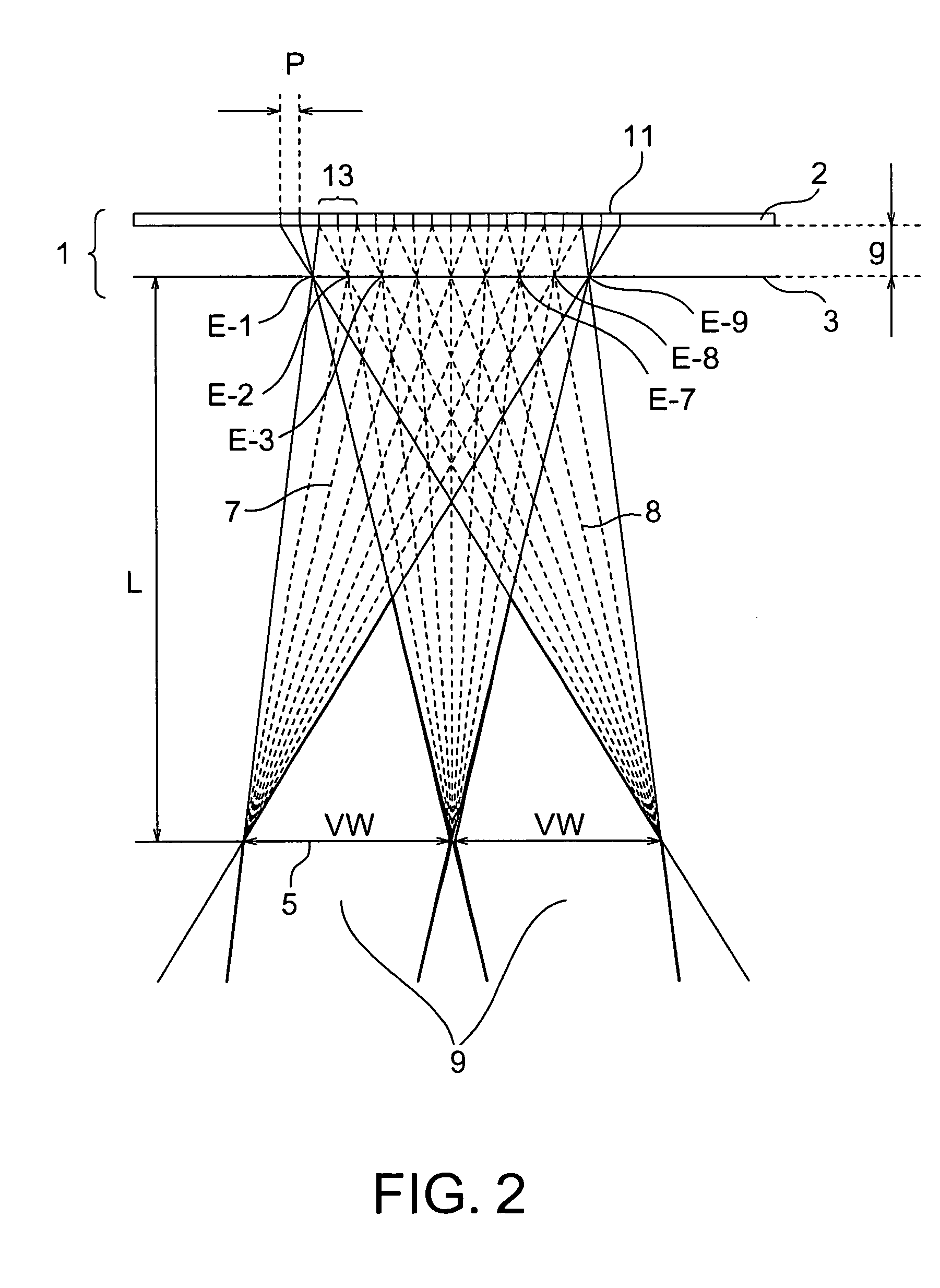
[0078] In this Example, the two-dimensional image display apparatus shown in FIG. 1B was a liquid crystal display apparatus and it was provided at its front face side with an optical plate 3 and at its back face side with a back light (not shown). Specifically, as the liquid crystal display apparatus, UXGA—LCD panel [(Product Name: Inspiron 8500) and the number of pixels was 1900×1200, a screen size was 331.2 mm ×207 mm] was used. A pixel was formed in square having a size of 172.5 μm×172.5 μm, a horizontal width of each sub-pixel of red, green, blue was 57.5 cm, and a vertical width thereof was 12.5 μm, the sub-pixel being able to be driven independently. In an ordinary two-dimensional image display apparatus 2, one pixel is constituted of three sub-pixels of red, green and blue arranged laterally. In the Example, however, the two-dimensional image display apparatus 2 was used without applying this constraint to the apparatus. A mosaic arrangement was used as a color filter arrange...

example 3

[0088] A two-dimensional image display apparatus was disposed such that a display thereof was directed upwardly like Example 2 and a viewing zone division in a vertical direction was performed such that two viewers positioned so as to be opposed to each other on both long sides of the display were included in the divided viewing zones (see FIG. 11).

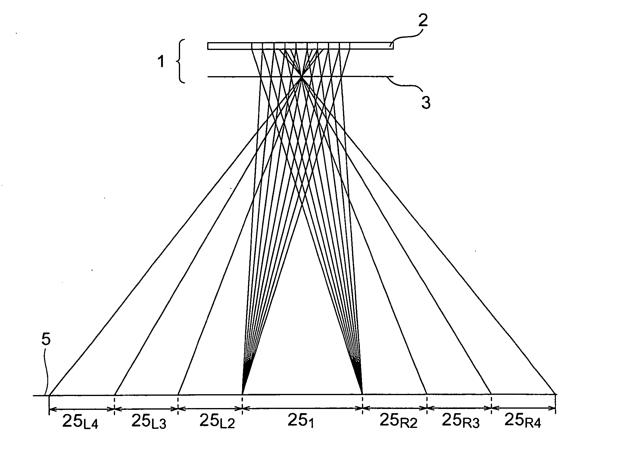
[0089] Designing was conducted such that the viewing zone width VW of the viewing zone 251 shown in FIG. 5 was 370 mm such that each of the viewers could view corresponding one of images within a range of 185 mm centering on a direction of 30.7° from the front of the display in a vertical direction in the viewing length L (=350 mm) assuming two viewers opposed to each other via a display with a display face directed upwardly. At that time, considering the gap (=0.7 mm) between the glass and the polarizing plate in the liquid crystal display, the vertical number of pixels for elemental image displaying (the number of parallaxes in a verti...

example 4

[0093] Such a configuration was employed that a two-dimensional image display apparatus was used like Example 1 and one viewer could view an image in the ranges of the viewing zones 25L2 and 25R2 shown in FIG. 5 with his / her both eyes. That is, designing was performed such that the viewing zone width VW of the viewing zone 251 shown in FIG. 5 was 42 mm such that one viewer could view a three-dimensional image within a range of 21 mm centering on directions of 2.58° from the front of the display in a horizontal direction leftward and rightward in the viewing distance L (=700 mm) (see FIG. 18). That is, the center of the viewing zone coincided with the interpupilliary distance (63 mm). At that time, the gap g was obtained in the following manner. g=700×(0.044×16) / 42=11.7⁢ ⁢(mm)

[0094] Specifically, as a thickness gr of a lenticular sheet made from PMMA, the following value was set from the equation (3) by subtraction of a gap gs (=0.8 mm) between a glass and a polarizing plate in the ...


PUM


Abstract

The present invention can provide an image display apparatus which where viewing zones can be provided on at least two regions spaced from each other. The image display apparatus is provided with a two-dimensional image display apparatus where a plurality of pixels are arranged in a two-dimensional manner and an optical plate which has a plurality of exit pupils and changes regions where image information pieces displayed on the pixels are viewed for the respective pixels by controlling light ray directions from the pixels, where a pixel group for elemental image being a plurality of pixels corresponds to one exit pupil of the exit pupils, image information corresponding to a position where each pixel is viewed via the exit pupil is displayed is displayed on each pixel for elemental image displaying, and the pixel group for elemental image displaying is provided so as to be separated to two or more regions.

Description

CROSS-REFERENCE TO RELATED APPLICATION [0001] This application is based upon and claims the benefit of priority from prior Japanese Patent Application No. 2005-92099 filed on Mar. 28, 2005 in Japan, the entire contents of which are incorporated herein by reference. BACKGROUND OF THE INVENTION [0002] 1. Field of the Invention [0003] The present invention relates to an image display apparatus for displaying a two-dimensional image or a three-dimensional image, which has two or more viewing zones spaced from one another. [0004] 2. Related Art [0005] In a commonly used two-dimensional image display apparatus, one or the same image can be viewed in any direction. However, in such a case that two viewers or persons opposed to each other via a two-dimensional image display apparatus with a display plane placed horizontally, which is positioned therebetween, or two viewers (persons) seating on a driver's seat and a front passenger's seat positioned on both sides of a car navigation system a...

Claims


Application Information

Patent Timeline
IPC IPC(8): H04N13/04H04N15/00G02B30/27G02B30/30
CPCG02B27/2214H04N13/0404H04N13/0409H04N13/305H04N13/31G02B30/27G02B30/30
Inventor FUKUSHIMA, RIEKOHIRAYAMA, YUZO
Owner KK TOSHIBA
Why Eureka
Try Eureka