Image forming apparatus, information processing method, and recording medium

a technology information processing method, which is applied in the direction of dot-and-dash receiving apparatus, program control, instruments, etc., can solve the problem that certain versions of image forming apparatus might not work properly

Active Publication Date: 2006-10-05
RICOH KK
View PDF10 Cites 18 Cited by
  • Summary
  • Abstract
  • Description
  • Claims
  • Application Information

AI Technical Summary

Benefits of technology

[0008] The present invention may solve the problem described above. A preferred embodiment of the present invention may prevent problems due to incompatibility between an image forming apparatus available in various models and versions and an application available in various models and versions for the image forming apparatus.
[0012] With the above described image forming apparatuses, problems due to incompatibility between the image forming apparatuses and applications for the image forming apparatuses can be prevented.

Problems solved by technology

Due to such variety of models and versions, a certain version of an application that works properly in a certain model and a certain version of an image forming apparatus might not work properly in a different model and a different version of an image forming apparatus.

Method used


Image

  • Image forming apparatus, information processing method, and recording medium
  • Image forming apparatus, information processing method, and recording medium
  • Image forming apparatus, information processing method, and recording medium

Examples


first embodiment

(1) First Embodiment

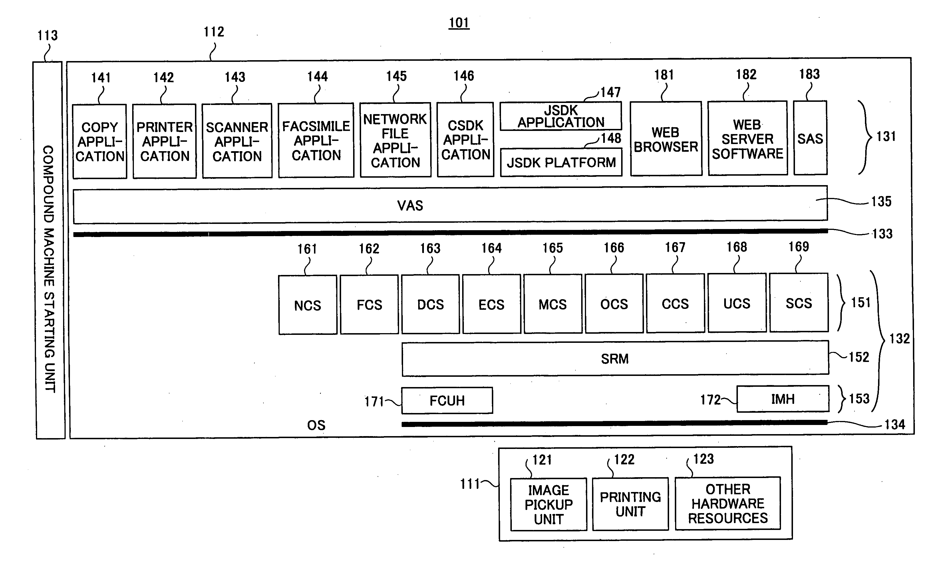
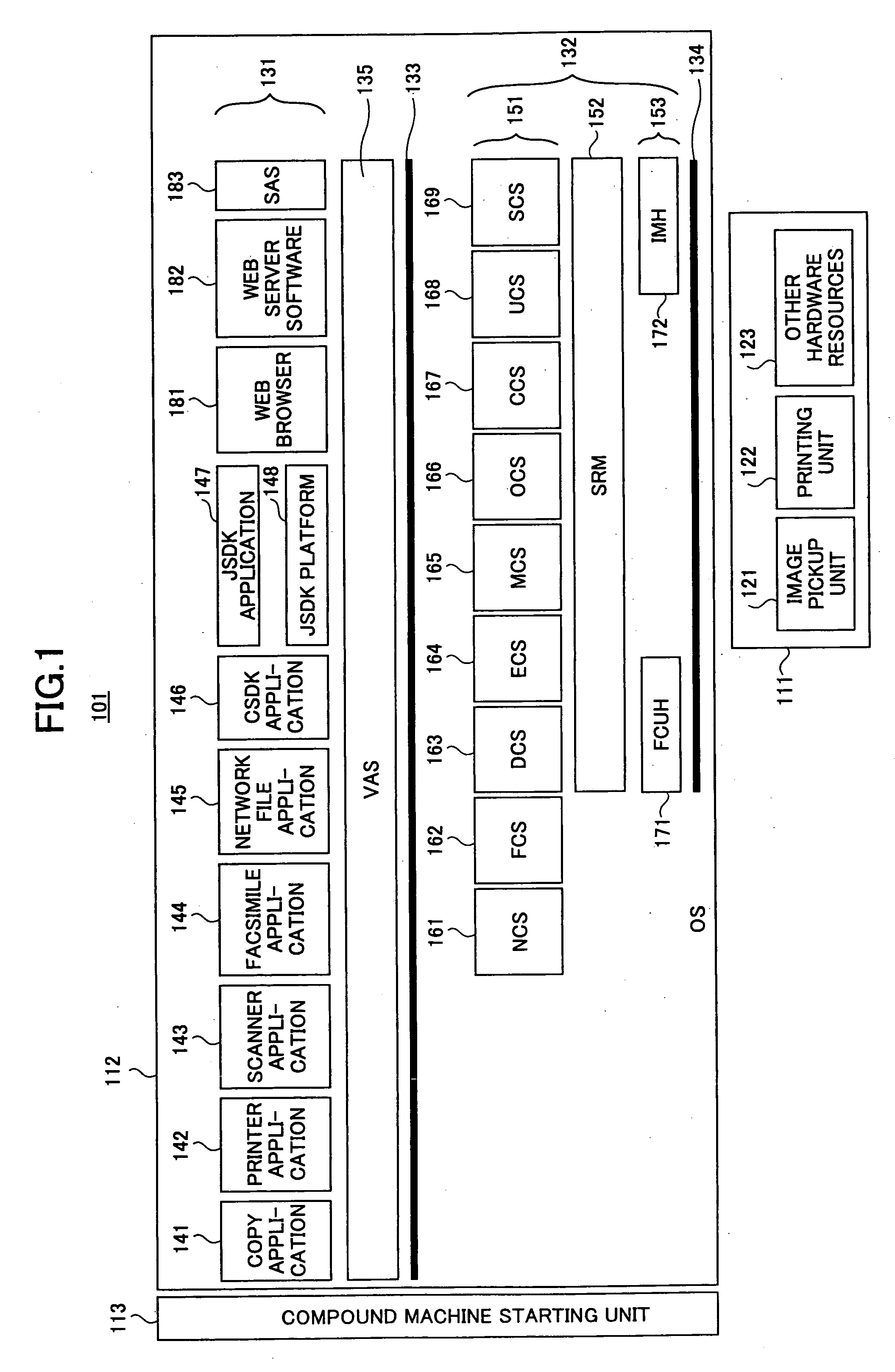
[0062]FIG. 7 is a diagram for explaining startup control of the JSDK application 147 according to a first embodiment.

[0063] In the first embodiment, the JSDK application 147 of FIG. 7 is illustrated as an example. The JSDK application 147 of FIG. 7 is held in the SD memory card 235 loaded in the SD memory card slot 234. The SAS 183 can start the JSDK application 147 of FIG. 7 in the compound machine 101 from the SD memory card 235 loaded in the SD memory card slot 234.

[0064] The JSDK application 147 of FIG. 7 is available in Ver. 1.0, Ver. 1.1, Ver. 1.2, Ver. 2.0, and Ver. 3.0. The JSDK application 147 of FIG. 7 is Ver. 2.0. The version of the VAS 135 that matches the version “Ver. 2.0” of the JSDK application 147 of FIG. 7 is “Ver. 3.0”. Accordingly, if the version of the VAS 135 is Ver. 3.0 or higher, since the version of the VAS 135 is compatible with the version of the JSDK application 147, the JSDK application 147 works properly. However, if the version of...

second embodiment

(2) Second Embodiment

[0071]FIGS. 9A and 9B are diagrams for explaining startup control of the JSDK application 147 according to a second embodiment.

[0072] In the second embodiment, the JSDK applications 147 of FIGS. 9A and 9B are illustrated as examples. In each of the compound machines 101 of FIGS. 9A and 9B, the JSDK application 147 is held in the SD memory card 235 loaded in the SD memory card slot 234. The SAS 183 can start the JSDK application 147 in the compound machine 101 from the SD memory card 235 loaded in the SD memory card slot 234.

[0073] Although both the compound machine 101 of FIG. 9A and the compound machine of FIG. 9B correspond to the compound machine 101 of FIG. 1, the compound machine 101 of FIG. 9A and the compound machine of FIG. 9B are different models. The compound machine 101 of FIG. 9A is a color compound machine, whereas the compound machine 101 of FIG. 9B is a monochrome compound machine. Accordingly, the types of supported functions are different betw...

third embodiment

(3) Third Embodiment

[0081]FIG. 11 is a diagram for explaining startup control of the JSDK application 147 according to a third embodiment.

[0082] In the third embodiment, the JSDK application 147, a CVM 555A, and CVM 555B of FIG. 11 are illustrated as examples. The JSDK application 147, the CVM 555A, and the CVM 555B of FIG. 11 are stored in the SD memory card 235 loaded in the SD memory card slot 234. The SAS 183 can start the JSDK application 147, the CVM 555A, and the CVM 555B of FIG. 11 in the compound machine 101 from the SD memory card 235 loaded in the SD memory card slot 234.

[0083] In this embodiment, the models of the image forming apparatus are managed as “model groups” such as “a 2004 second half model group”, “a 2005 first half model group”, and “a 2005 second half model group”. Such management allows development of the image forming apparatus on a per-model group basis. Java™ execution environments are changed on the per-model group basis. Accordingly, in this embodime...


PUM


Abstract

An image forming apparatus including an application is disclosed. The image forming apparatus includes a determining unit that, when the application starts in the image forming apparatus, checks first information indicating a function to be used by the application against second information indicating a function supported by the image forming apparatus so as to determine whether the function to be used by the application is executable, and changes operations of the application according to a determination result. The determining unit is automatically updated if the determining unit does not support a structure of the first information or a structure of the second information.

Description

BACKGROUND OF THE INVENTION [0001] 1. Field of the Invention [0002] The present invention relates to an image forming apparatus such as a copier, a printer, a scanner, a facsimile, a multifunction machine, and a compound machine; an information processing method; and a recording medium such as an SD card. [0003] 2. Description of the Related Art [0004] In recent year, multifunction machines and compound machines having copy, printer, scanner, and facsimile functions have been available in the market. The multifunction machines and the compound machines can print images on printing paper when used as copiers or printers, scan images from original documents when used as copiers or scanners, and send and receive images to and from other communication apparatuses via telephone lines when used as facsimiles. [0005] Patent Document 1 discloses an invention related to an image forming apparatus having copy, printer, scanner, and facsimile functions. The image forming apparatus is provided ...

Claims


Application Information

Patent Timeline
Patent Type & Authority Applications(United States)
IPC IPC(8): G09C3/08H04L15/34H04L9/00
CPCG06F9/445H04N1/00912G06F9/542H04N1/32561H04N2201/0094H04N1/32496
Inventor OHISHI, TSUTOMU
Owner RICOH KK
Why Eureka
Try Eureka