Image forming apparatus, information processing method, and recording medium
a technology of image forming apparatus and information processing method, which is applied in the direction of program control, interprogram communication, multi-programming arrangement, etc., can solve the problem that certain versions of the image forming apparatus might not work properly
- Summary
- Abstract
- Description
- Claims
- Application Information
AI Technical Summary
Benefits of technology
Problems solved by technology
Method used
Image
Examples
first embodiment
(1) First Embodiment
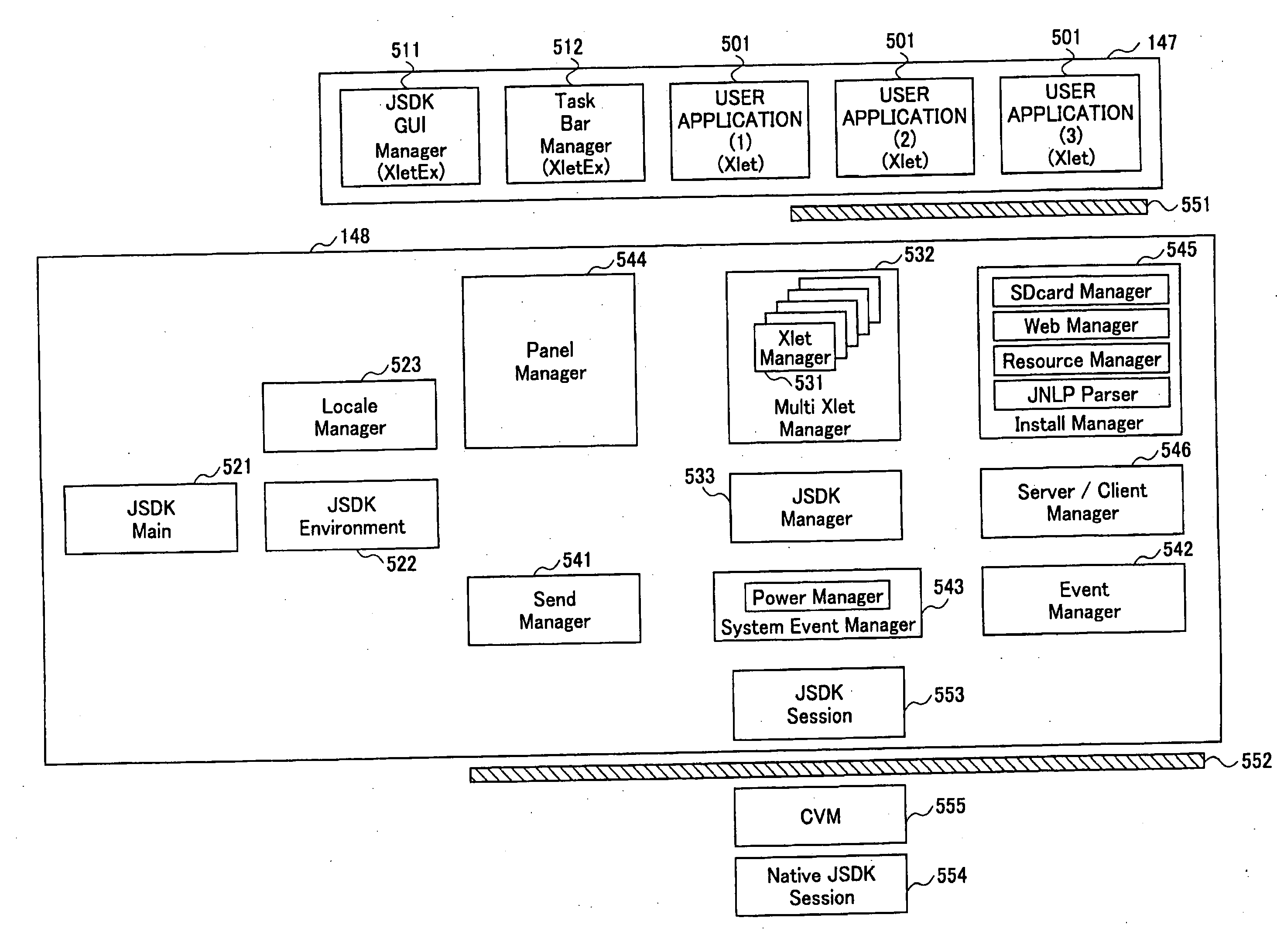
[0063]FIG. 7 is a diagram for explaining startup control of the JSDK application 147 according to a first embodiment.
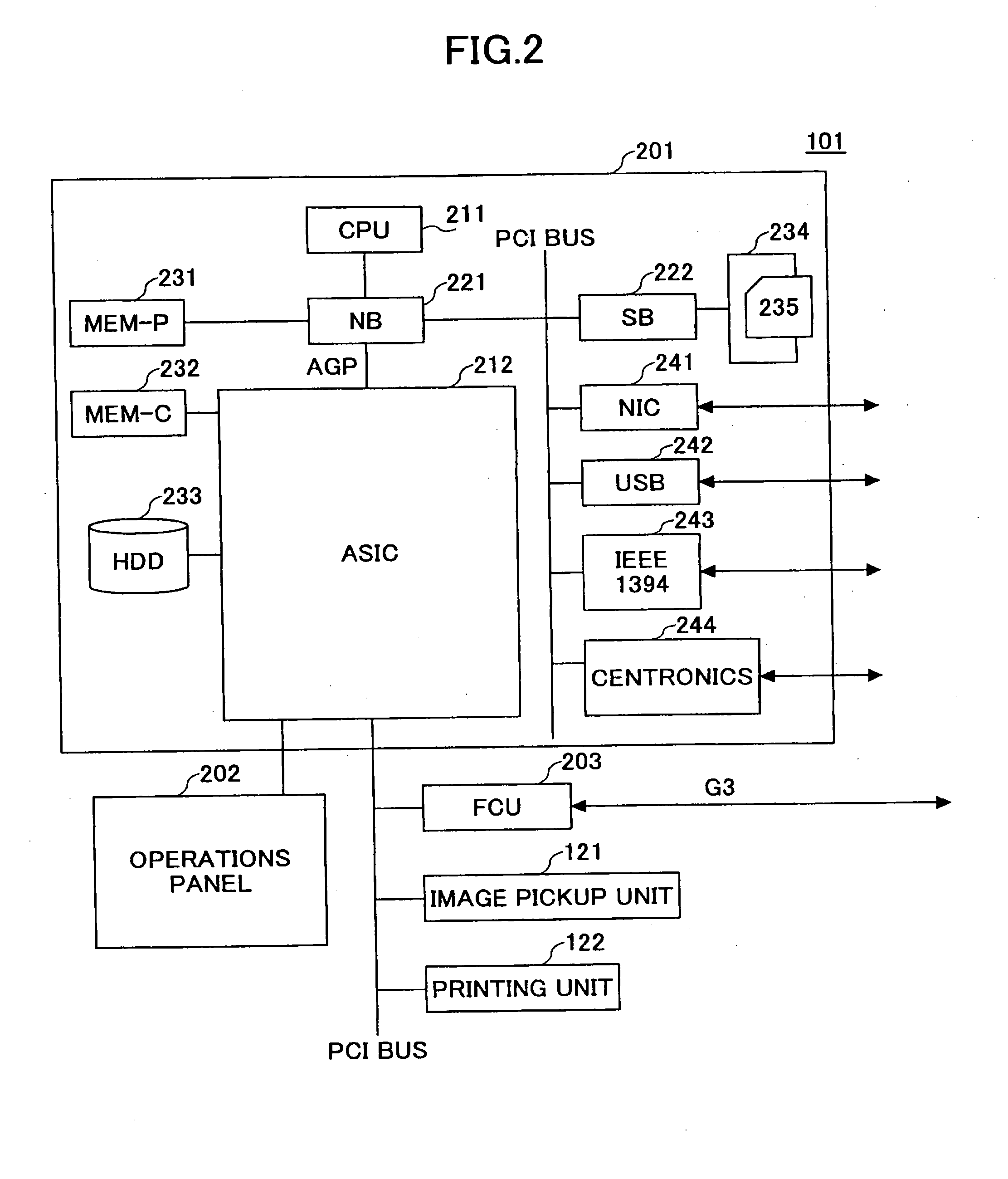
[0064]In the first embodiment, the JSDK application 147 of FIG. 7 is illustrated as an example. The JSDK application 147 of FIG. 7 is held in the SD memory card 235 loaded in the SD memory card slot 234. The SAS 183 can start the JSDK application 147 of FIG. 7 in the compound machine 101 from the SD memory card 235 loaded in the SD memory card slot 234.
[0065]The JSDK application 147 of FIG. 7 is available in Ver. 1.0, Ver. 1.1, Ver. 1.2, Ver. 2.0, and Ver. 3.0. The JSDK application 147 of FIG. 7 is Ver. 2.0. The version of the VAS 135 that matches the version “Ver. 2.0” of the JSDK application 147 of FIG. 7 is “Ver. 3.0”. Accordingly, if the version of the VAS 135 is Ver. 3.0 or higher, since the version of the VAS 135 is compatible with the version of the JSDK application 147, the JSDK application 147 works properly. However, if the version of the...
second embodiment
(2) Second Embodiment
[0072]FIGS. 9A and 9B are diagrams for explaining startup control of the JSDK application 147 according to a second embodiment.
[0073]In the second embodiment, the JSDK applications 147 of FIGS. 9A and 9B are illustrated as examples. In each of the compound machines 101 of FIGS. 9A and 9B, the JSDK application 147 is held in the SD memory card 235 loaded in the SD memory card slot 234. The SAS 183 can start the JSDK application 147 in the compound machine 101 from the SD memory card 235 loaded in the SD memory card slot 234.
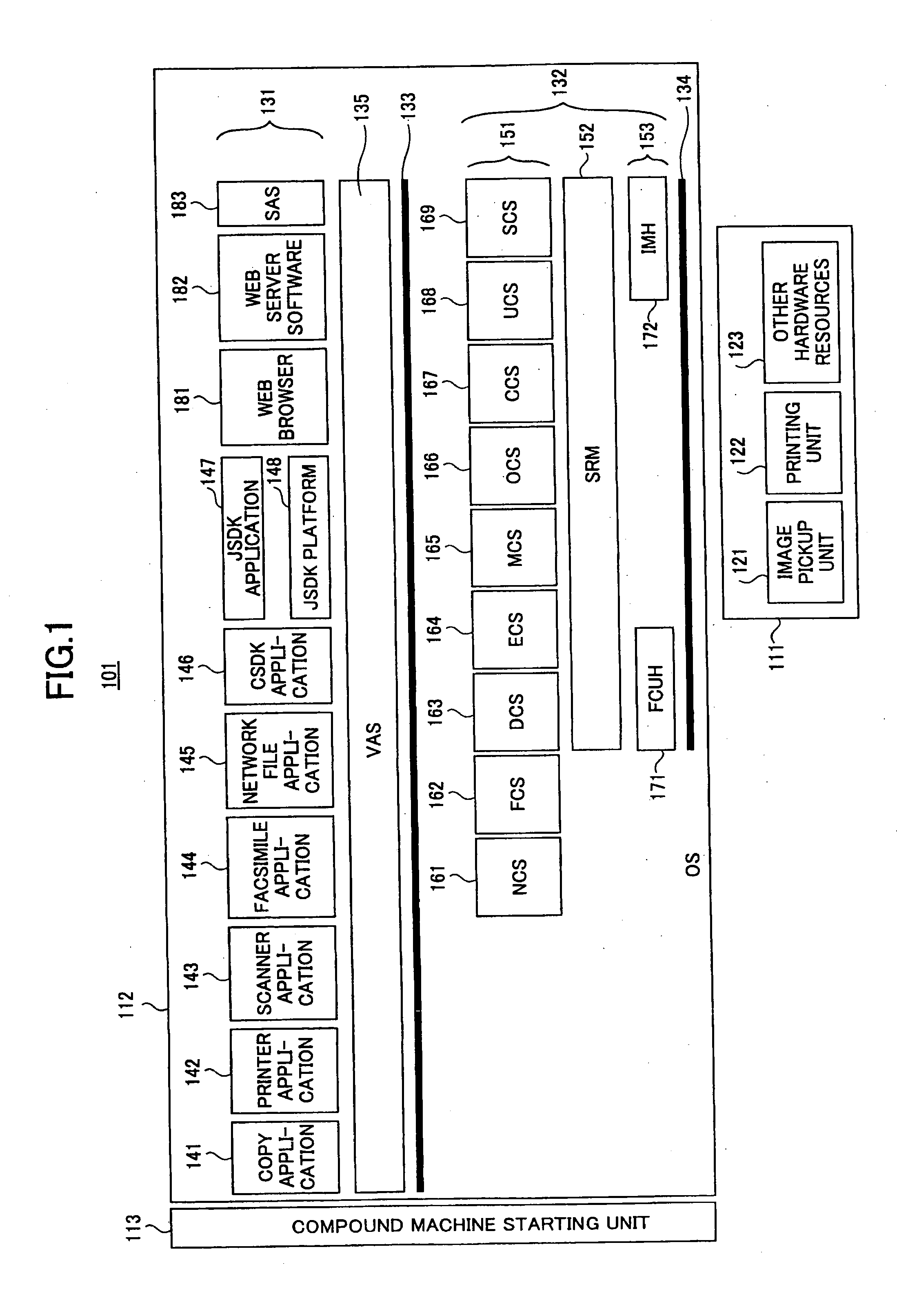
[0074]Although both the compound machine 101 of FIG. 9A and the compound machine of FIG. 9B correspond to the compound machine 101 of FIG. 1, the compound machine 101 of FIG. 9A and the compound machine of FIG. 9B are different models. The compound machine 101 of FIG. 9A is a color compound machine, whereas the compound machine 101 of FIG. 9B is a monochrome compound machine. Accordingly, the types of supported functions are different between ...
third embodiment
(3) Third Embodiment
[0082]FIG. 11 is a diagram for explaining startup control of the JSDK application 147 according to a third embodiment.
[0083]In the third embodiment, the JSDK application 147, a CVM 555A, and CVM 555B of FIG. 11 are illustrated as examples. The JSDK application 147, the CVM 555A, and the CVM 555B of FIG. 11 are stored in the SD memory card 235 loaded in the SD memory card slot 234. The SAS 183 can start the JSDK application 147, the CVM 555A, and the CVM 555B of FIG. 11 in the compound machine 101 from the SD memory card 235 loaded in the SD memory card slot 234.
[0084]In this embodiment, the models of the image forming apparatus are managed as “model groups” such as “a 2004 second half model group”, “a 2005 first half model group”, and “a 2005 second half model group”. Such management allows development of the image forming apparatus on a per-model group basis. Java™ execution environments are changed on the per-model group basis. Accordingly, in this embodiment, ...
PUM
 Abstract
Description
Claims
Application Information
 - R&D
- Intellectual Property
- Life Sciences
- Materials
- Tech Scout
- Unparalleled Data Quality
- Higher Quality Content
- 60% Fewer Hallucinations
Browse by: Latest US Patents, China's latest patents, Technical Efficacy Thesaurus, Application Domain, Technology Topic, Popular Technical Reports.
© 2025 PatSnap. All rights reserved.Legal|Privacy policy|Modern Slavery Act Transparency Statement|Sitemap|About US| Contact US: help@patsnap.com


