Tray locking device for optical disc drive

a locking device and optical disc technology, applied in the direction of information storage, instruments, data recording, etc., can solve the problems of hook stop, unexpected slipping of tray from optical disc drive, late stop time of motor, etc., and achieve the effect of simple structure and saving drive spa

Inactive Publication Date: 2006-11-23
LITE ON IT
View PDF4 Cites 10 Cited by
  • Summary
  • Abstract
  • Description
  • Claims
  • Application Information

AI Technical Summary

Benefits of technology

[0010] The object of the present invention relates to a tray locking device for an optical disc drive which has a simply structure and thus saves its space occupied in the drive. The present tray locking device for optical disc drive resolves the problem of breaking of memory metal during the drop test for optical disc drive.

Problems solved by technology

However, in a drop test for optical disc drive, the magnetic attraction is not enough to hold the hook in engaging with the lock pin, therefore the tray will slide out from the optical disc drive unexpectedly.
However, since the transmission of stopping signal from the switch might delay, the stop time of the motor is also late and the hook stops at an inappropriate position.
In this regards, it might result in the locking device jamming.
Moreover, the solenoid and the DC motor driving type locking devices both include so many mechanical members or the hook driving manner is complex, it will occupy a lot of device space and is not easily to assemble so the assembly cost is increased.
However, although the use of memory metal line to control the locking device simplifies the constituting members and effectively drive the hook to release from the lock pin, but in the drop test for optical disc drive, the memory metal line will be broken down due to the dropping force.
Thus it could not pass the drop test for optical disc drive.

Method used


Image

  • Tray locking device for optical disc drive
  • Tray locking device for optical disc drive
  • Tray locking device for optical disc drive

Examples


Embodiment Construction

[0029] The present invention is illustrated in more detail by reference the following preferred embodiments which are only used for illustration without limiting the scope of the present invention.

[0030] The present invention will be illustrated in more detail by reference to an embodiment in which the present tray locking mechanism is provided on a tray and a lock pin is provided on the inner wall of a housing. However, the present invention is not limited to the mentioned above. This is, the tray locking mechanism could be provided on the inner wall of a housing and a lock pin could be provided on a tray, as long as the tray locking mechanism is effectively engaged with the lock pin.

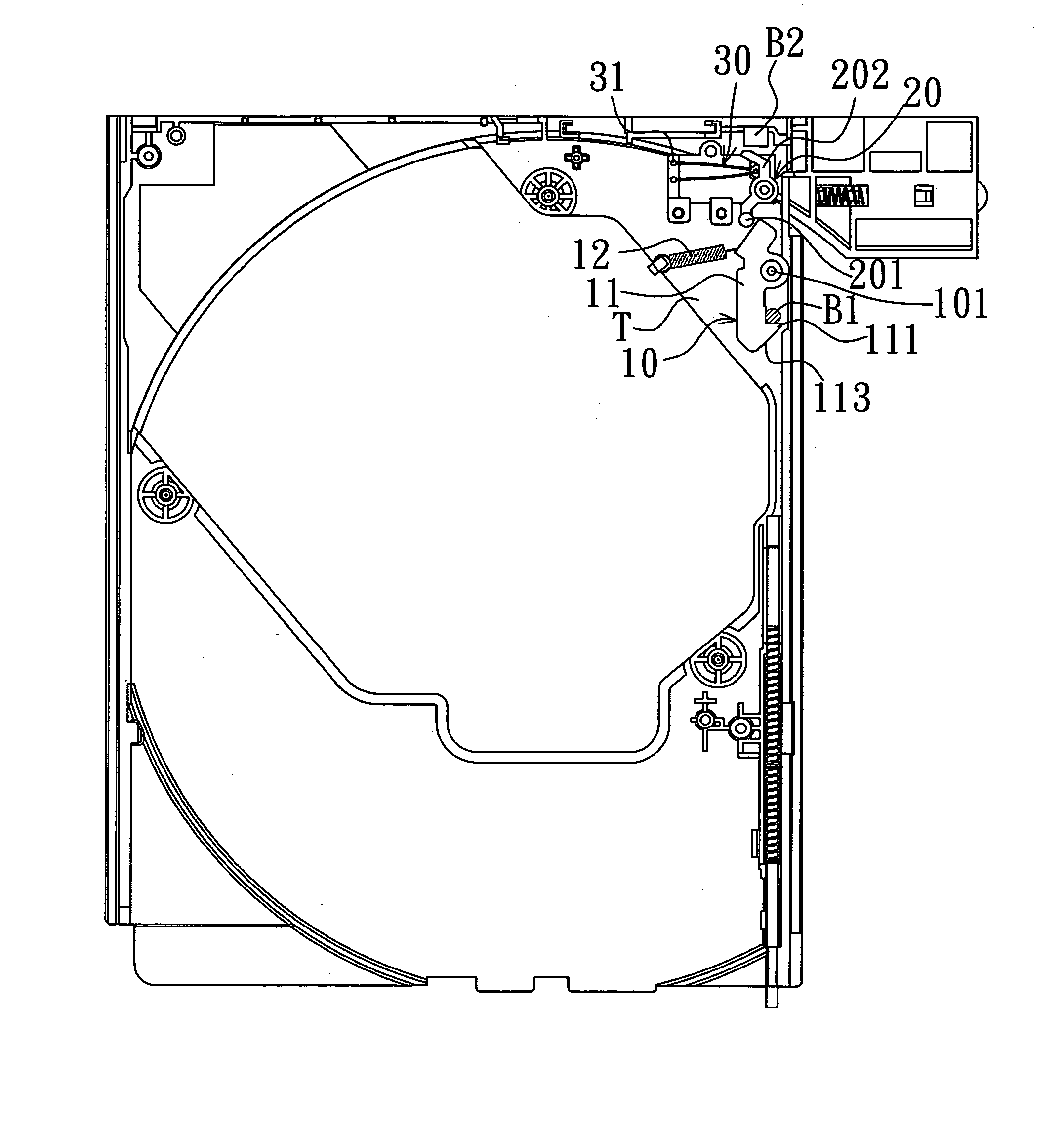
[0031] Please refer to FIG. 3. FIG. 3 is a schematic view showing an optical disc drive including the tray locking device of the present invention, in which the tray is carried out from the housing.

[0032] The present invention relates to a tray locking device for an optical disc drive in which the o...


PUM

PropertyMeasurementUnit
lengthsaaaaaaaaaa
temperatureaaaaaaaaaa
lengthaaaaaaaaaa

Abstract

The present invention relates to a tray locking device for optical disc drive, which uses a driving element and a memory metal having different lengths at different temperature conditions to control the movement of the driving element to drive a locking mechanism. Accordingly, it attains the objects of simplifying its structure and saving assembling space, and avoids the breakage of the memory metal attributed to shocking force during drop test.

Description

[0001] This Non-provisional application claims priority under 35 U.S.C. § 119(a) on Patent Application No(s). 094115921 filed in Taiwan, Republic of China on May 17, 2005, the entire contents of which are thereby incorporated by reference. FIELD OF THE INVENTION [0002] The present invention relates to a tray locking device for optical disc drive, particular to a tray locking device for optical disc drive which is driven by a memory metal. BACKGROUND OF THE INVENTION [0003] The tray locking device used in the slim type optical disc drive, according to its driving manner, is classified into a solenoid driving type and direct current (DC) motor driving type. [0004] The solenoid driving type tray locking device mainly uses a magnetic attraction generated by the solenoid to disengage a hook from a lock pin and allow the tray locking in the optical disc drive. However, in a drop test for optical disc drive, the magnetic attraction is not enough to hold the hook in engaging with the lock p...

Claims


Application Information

Patent Timeline
Patent Type & Authority Applications(United States)
IPC IPC(8): G11B17/04
CPCG11B17/056
Inventor YANG, MIN CHENGYEH, SHIH LIN
Owner LITE ON IT
Why Eureka
Try Eureka